Classic Particle Creation
![]()
nFX Particles
This option is used to generate a uniformly distributed particle for the nanoFluidX (nFX) solver. The particles form a grid in the global XYZ axis with one point at the origin. The output from this operation is a HEX mesh. The SPH particles are the nodes that define the hex elements.The input geometry can be CAD or FE models.
A model typically has solids that are stationary (outer container for example), solids that move (gears, shafts, etc.) and sometimes solids that represents the liquid and gas inside the container. The stationary part is modelled as is or, to improve solver performance, the wetted surface is identified and a thick region is created. The moving parts are modelled as hollow solids. If the fluid regions are represented as solids then they are meshed as is. In the absence of solids for the fluid regions, the liquid gas interface is defined by a plane and the software automatically creates particles for the liquid and air regions.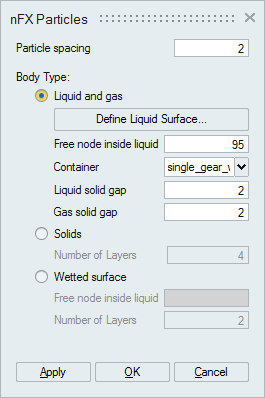
Particle spacing
Particle spacing is the distance between adjacent particles in the global coordinate axis. The particles are uniformly distributed along the global XYZ axis. This spacing is used when generating the particles for stationary parts, moving parts and the fluid regions.
Body Type: Liquid and Gas
This option helps define and create the liquid and gas regions inside the container. This is useful when the CAD or FE model does not have a separate body for the liquid and gas.
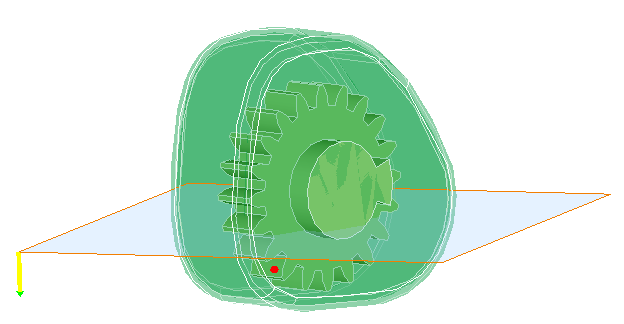
Define Liquid Surface
The "Define Liquid Surface" helps define the planar surface that separates the liquid and gas. The plane normal points to the liquid region.
Free node inside liquid
In addition a free node inside the liquid (oil) is to be selected.
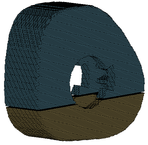
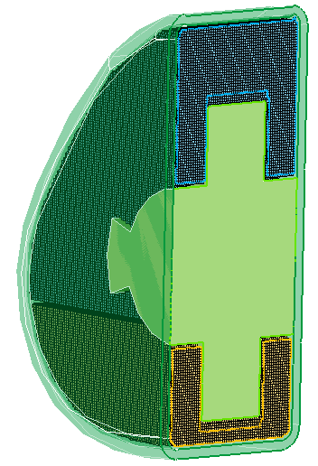
The resultant liquid and the gas regions are shown below.
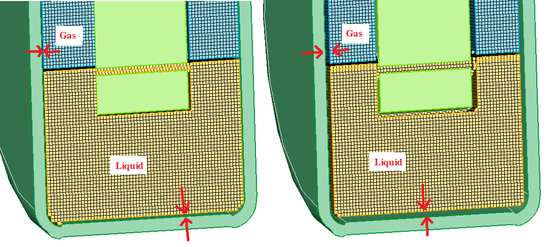
Liquid solid gap defines the minimum distance from the solid surface within which no particles should be created in the liquid region.
Gas solid gapGas solid gap defines the minimum distance from the solid surface within which no particles should be created in the gas region.
Outputs with "0" liquid/gas solid gap and "2" liquid/gas solid gap are shown below.
Body Type: Solid
This option help create particles for the gears, shafts, or casings which are solids. Particles will be created inside the solid region. To reduce model size, users can model the solids as a thick solid (hollow inside) without impacting the results. To facilitate this, users can specify a finite number of layers of particles needed from the solid surface. If the number of layers is specified as 0, all the particles inside the solids will be created. This can also be used for liquid or gas regions modelled as solids in the geometry.
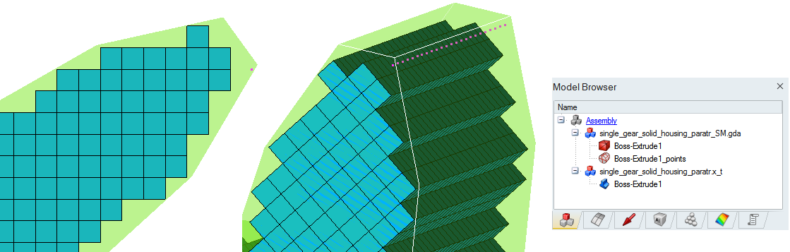
Output with 4 layers of particles is shown below:
Additional points that are inside the body (input volume) but not part of a complete hex will be created as a point body.
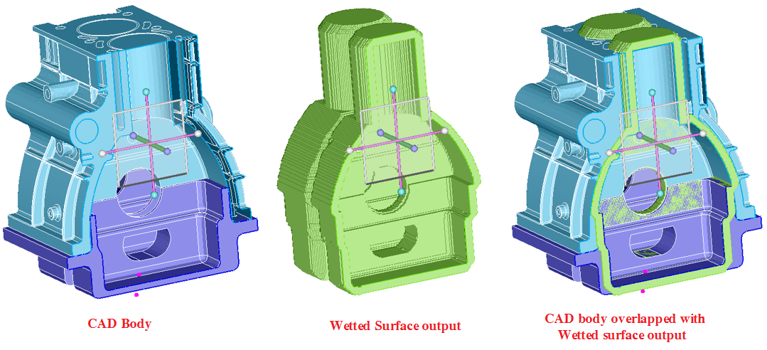
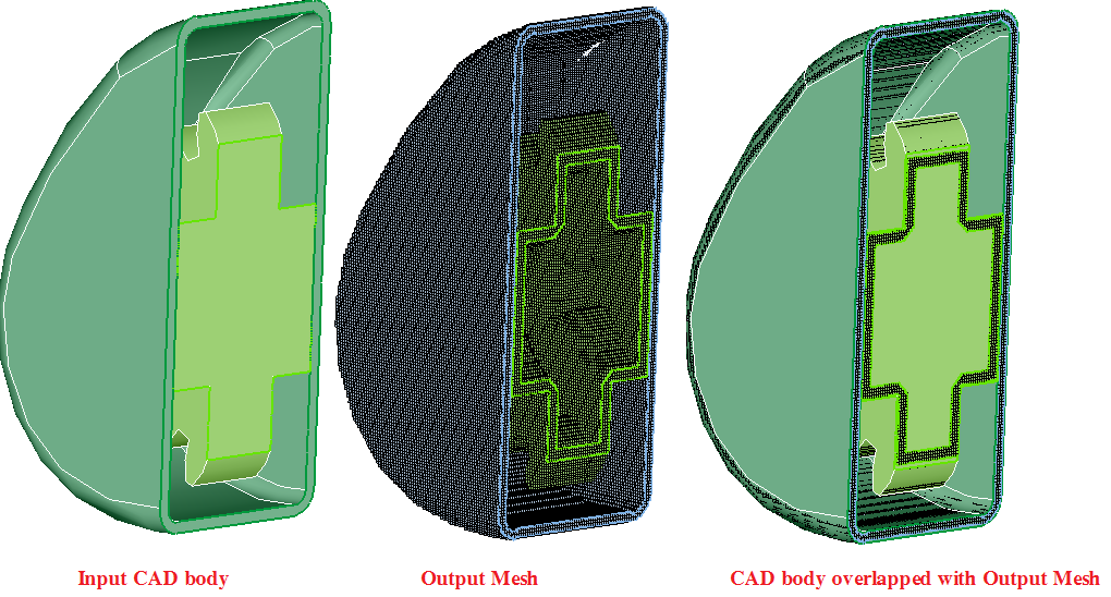
Body Type: Wetted surface
Sometimes the outer casing can have features like bolt holes, ribs, etc. which do not impact the solution. It is more efficient to generate the model without these features. This is achieved by identifying solids that define the container (should not include the moving parts and should be closed: should not have gaps bigger than the particle distance) and a point inside the container where the fluids are present. The software will identify the wetted surface (surface that is touched by the fluids) and create several layers of particles away from the wetted surface. A free node inside the fluid and a required number of layers of particles should be specified. The wetted surfaces for the liquid will be automatically identified.