Set Node ID
![]()
Set Node ID tool is used to renumber the nodes using the following options.
Selected Nodes
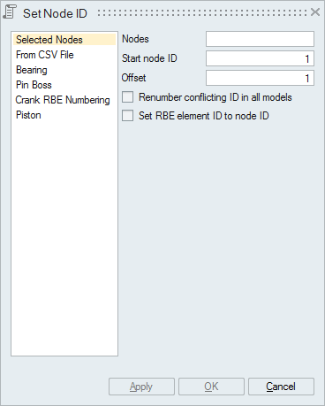 Nodes
NodesNodes selected for renumbering. The nodes will be renumbered in the selected order.
Start node IDStarting ID for the selected nodes.
OffsetThe value with which the ID is offset for the selected nodes. It is possible to offset by both positive and negative values.
Renumber conflicting ID in all modelsWhen the ID to be assigned is already assigned to another node, that node will be renumbered to the maximum unique ID of the model. Turn this toggle ON, to have unique ID across all the models.
Set RBE element ID to node IDThis toggle is used to renumber the selected center node and its connected RBE element to same ID.
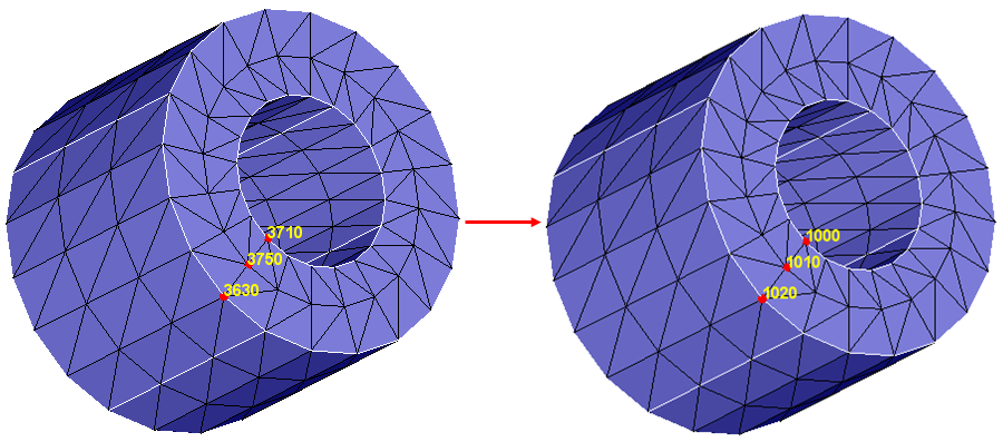
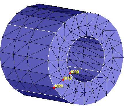
ExampleIn the below example, nodes are renumbered with 1000 as start ID and 10 as offset value.
In the below example, both the RBE element and its center node renumbered to same ID.
Input
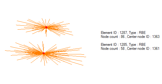
For the selected nodes, its connected RBE element is also renumbered.
From CSV File
This is used to renumber nodes using the coordinates and the IDs specified in the CSV file.
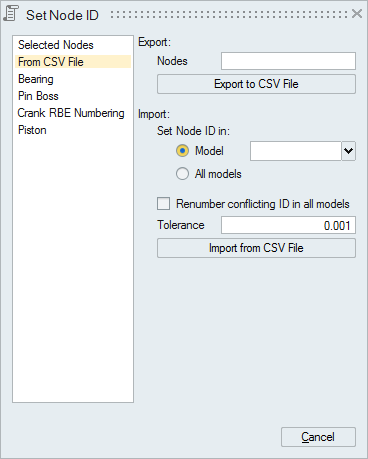 Export
Selected nodes coordinate and its ID can be exported in a CSV file.
Example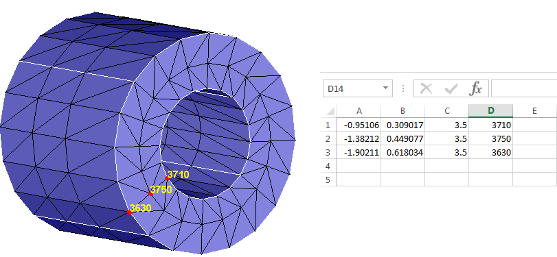 Import
Node that is closest within the Tolerance to the given coordinate in the CSV file will be assigned with the corresponding ID.
- Model
Renumbers the nodes from the selected model.
- All Models
Renumbers the nodes from all the available models.
- Renumber conflicting ID in all the models
When the ID to be assigned is already assigned to another node, that node will be renumbered to the maximum unique ID of the model. Turn this toggle ON, to have unique ID across all the models.
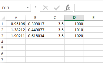
Example
Input File:
Nodes that got renumbered:
Bearing
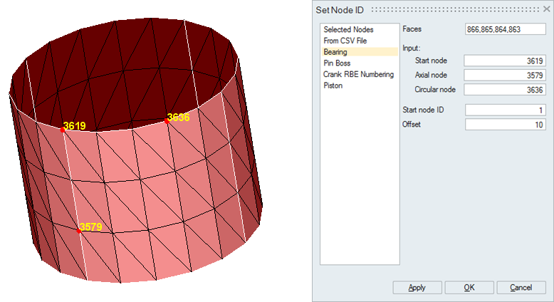
This is used to renumber the nodes of cylindrical faces (full and partial) in the axial direction.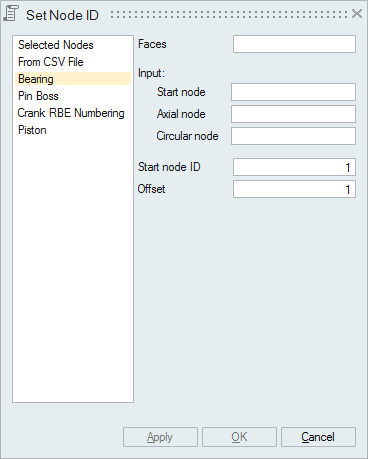 Start
node
Start
nodeThe node from which the numbering has to be started.
Axial nodeThe node that is used to specify the axial direction.
Circular nodeThe node that is used to specify the radial direction.
Start node IDThe ID from which the numbering has to be started.
OffsetThe value with which the ID is offset. It is possible to offset by both positive and negative values.
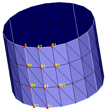
ExampleInput
Shown below some of the renumbered node ID:
Pin Boss
This is used to renumber the nodes of cylindrical faces in the radial direction.
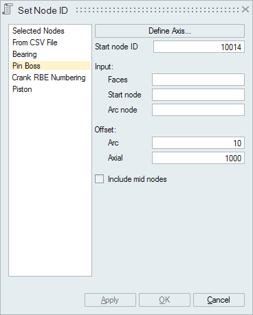 Start node
ID
Start node
IDThe ID from which the numbering has to be started.
Start nodeThe node from which the numbering has to be started.
Arc nodeThe node that is used to specify the radial direction.
Offset- Arc: ID offset value along the radial direction. It is possible to offset by both positive and negative values.
- Axial: ID offset value along the axial direction. It is possible to offset by both positive and negative values.
Turn this toggle ON to renumber the mid nodes.
ExampleInput
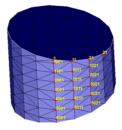
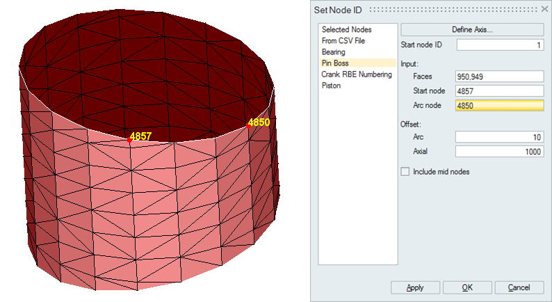 Output
Shown below some of the renumbered node ID:
Crank RBE Numbering
This option is used to renumber the RBE elements and their center nodes.
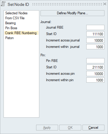 Define/Modify
Plane
Define/Modify
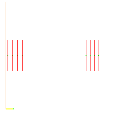
PlaneThis reference plane is used to arrange the journals and pins RBE elements. The renumber will start from the journal and pin that is closer to plane.
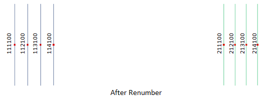
Start IDThe ID from which the renumbering has to be started can be specified here.
Increment across journalDifference in increment between the two adjacent journals.
Increment within journalDifference in increment between two adjacent RBEs within single journal.
Increment across pinDifference in increment between two adjacent pins.
Increment within pinDifference in increment between two adjacent RBEs within single pin.
ExampleInput
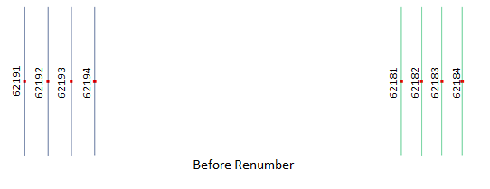
Output
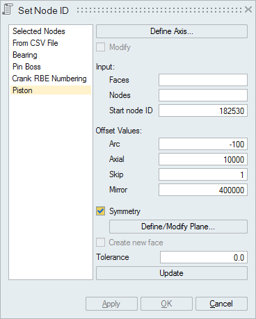
Piston
Edge Nodes
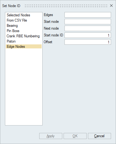 Edges
EdgesEdges selected for renumbering the nodes. The nodes will be renumbered based upon the start node and next node.
Start nodeStart node is selected for defining the start point. For open edge loops, start node is enough to define the direction.
Next NodeNext node is selected for defining the direction for closed edge loops. Next node should be the adjacent corner node of start node.
Start node IDStarting ID for the selected nodes.
OffsetThe value with which the ID is offset for the selected nodes. It is possible to offset by both positive and negative values.
Example for closed edge loopIn the below example, nodes are renumbered with 1000 as start ID and 2 as offset value.
InputFor closed edge loop, both start and next nodes are selected to define the direction.
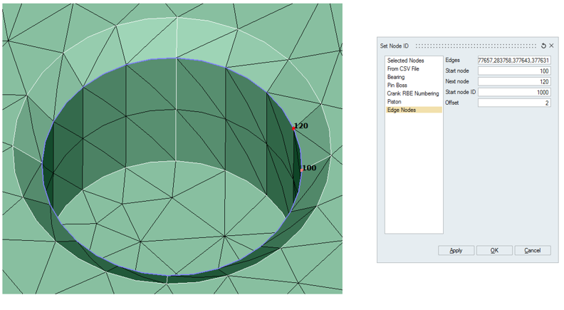 Output
Edge nodes (including mid nodes) are renumbered based on the direction given.
 Example for open
edge loop
Example for open
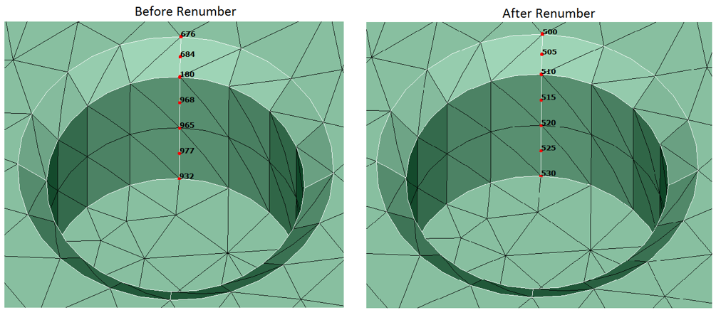
edge loopIn the below example, nodes are renumbered with 500 as start ID and 5 as offset value.
InputFor open edge loop, start node is selected to define the direction.
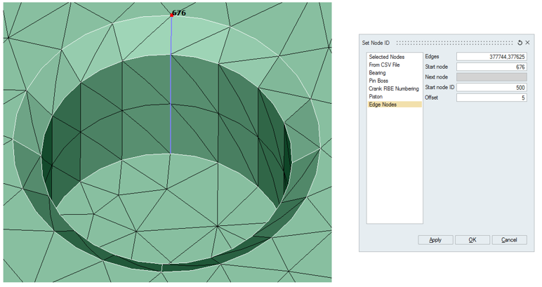 Output
Edge nodes (including mid nodes) are renumbered based on the direction given.