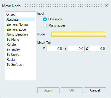
Move Node
![]()
This is used to relocate (move) or duplicate (copy) the nodes from the current position to the desired position.
Offset
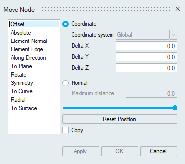 Coordinate
Nodes, edges or faces can be offset for the specified delta values along X, Y and Z direction. By default, nodes are moved in the global coordinate system. You can specify a local rectangular coordinate sytem for the offset.
NormalElements or faces can be offset along its normal direction for the specified distance.
Reset PositionThe slider bar is used to alter the node position. The modified node position can be restored to the initial position by clicking this button.
CopyBy default, the actual nodes will be moved. Turn this toggle ON to create orphan nodes at the new position.
ExampleIn the below example, nodes are offset along X axis for a distance of 1 unit.
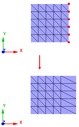
In the below example, face is offset along its normal direction for a distance of 5 units.
Absolute
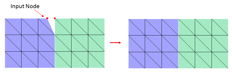
This is used to move the nodes to the specified coordinates. The coordinate values (X, Y and Z) can be entered manually or can be set by picking a node or a vertex.
Example
In the below example, the input node is moved to the other node location.
Element Normal
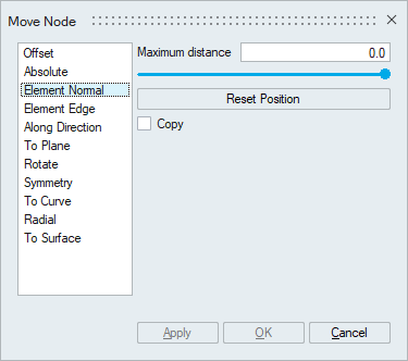
This is used to move the nodes in the normal direction of an element.
Maximum distanceMaximum distance the nodes can move. A default value is set based on the average distance of the element edges connected to the selected nodes. You can edit it.
Reset PositionThe slider bar is used to alter the node position. The modified node position can be restored to the initial position by clicking this button.
Copy
By default, the actual nodes will be moved. Turn this toggle ON to create orphan nodes at the new position.
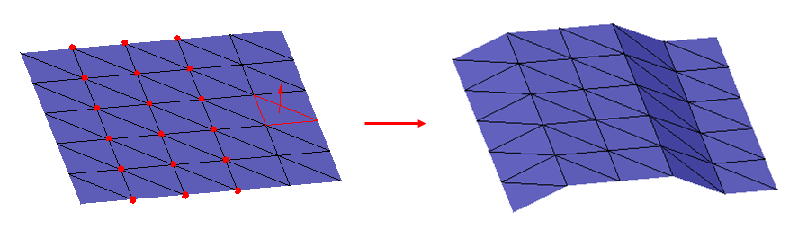
ExampleIn the below example, nodes are moved along the given element normal for a distance of 1 unit.
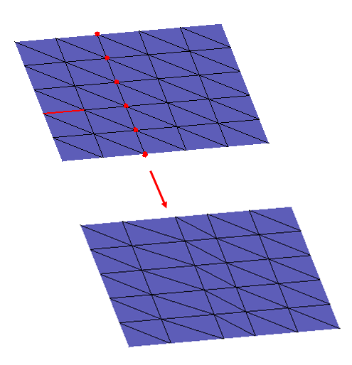
Element Edge
This is used to move the nodes in the direction of the element edge.
Maximum distanceMaximum distance the nodes can move. The length of the selected element edge is set as maximum distance. You can edit it.
Reset PositionThe slider bar is used to alter the node position. The modified node position can be restored to the initial position by clicking this button.
CopyBy default, the actual nodes will be moved. Turn this toggle ON to create orphan nodes at the new position.
ExampleIn the below example, nodes are moved along the given element edge direction.
Along Direction
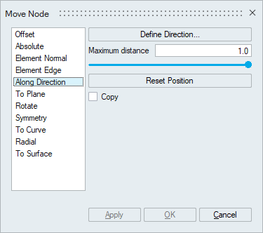
This is used to move the nodes in the defined direction.
Maximum distanceMaximum distance the nodes can move. A default value is set based on the inputs used for the direction definition. You can edit it.
Reset PositionThe slider bar is used to alter the node position. The modified node position can be restored to the initial position by clicking this button.
CopyBy default, the actual nodes will be moved. Turn this toggle ON to create orphan nodes at the new position.
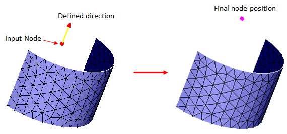
ExampleIn the below example, the selected node is moved along the defined direction for a distance of 3 units.
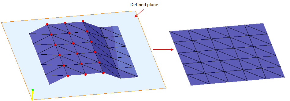
To Plane
This is used to move the nodes to a specific plane.
Define/Modify Plane
To define the plane.CopyBy default, the actual nodes will be moved. Turn this toggle ON to create orphan nodes at the new position.
ExampleIn the below example, nodes are moved to the specified plane.
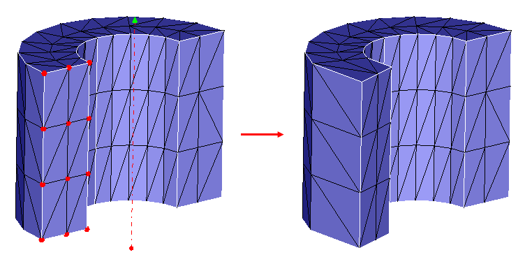
Rotate
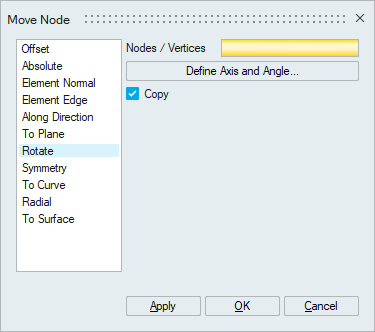
This is used to rotate the nodes about an axis.
Define Axis and AngleTo define the axis and the angle of rotation.
CopyBy default, orphan nodes are created at the new position. Turn this toggle OFF to rotate the actual nodes itself.
ExampleIn the below example, nodes are rotated in the positive direction of the rotation axis by 20 degrees.
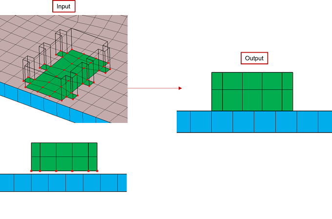
Symmetry
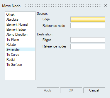
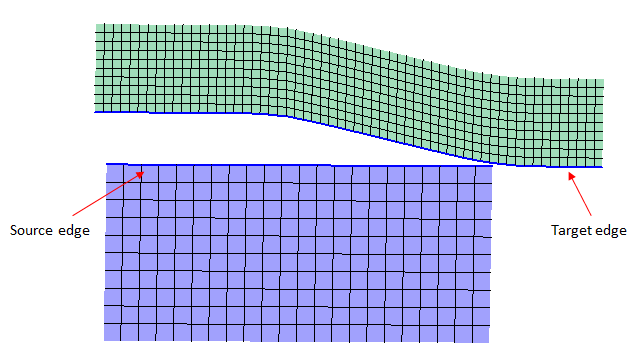
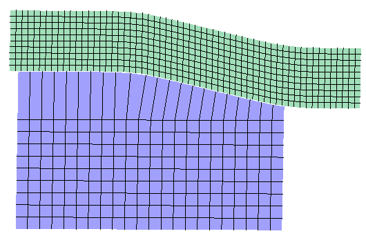
This option is used to move the nodes present in the destination edge in the same ratio as that of in the source edge. The ratio in which the nodes are present in the source edge will be used to arrange the nodes in the destination edge. The source and destination edge element count should be same.
Reference nodes are used to indicate the direction in which the nodes, in the destination edge, are to be sequenced. You can select multiple destination edges, provided you have to select respective reference node for each edge.
ExampleInput
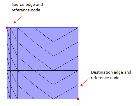
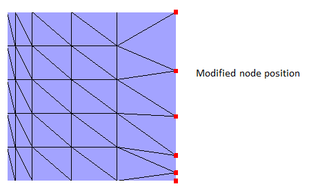
Output
Destination edge nodes moved with respect to the source edge node position.
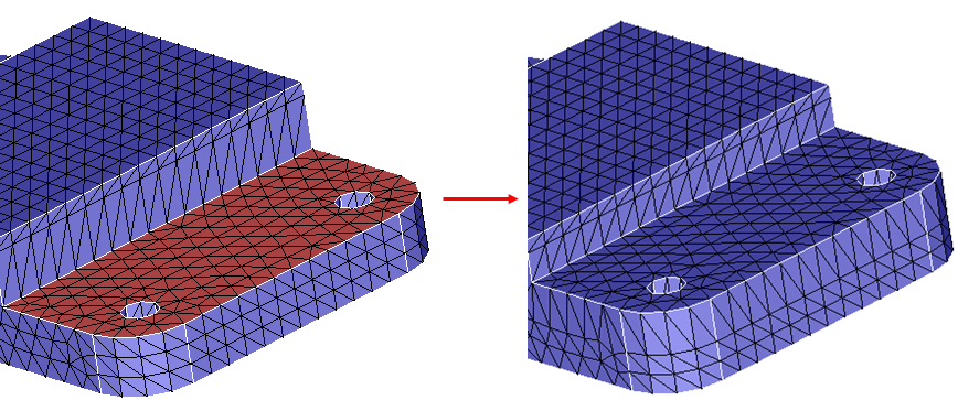
To Curve
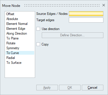
This is used to project the nodes or nodes of the source edges on to the target edges.
Use directionYou can use this option to define the direction of projection.
CopyBy default, the actual nodes will be projected. Turn this toggle ON to create orphan nodes at the new position.
ExampleInput
Output
Radial
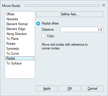
Radial offset
This is used to offset the nodes along the radial direction for the given offset Distance. The input can be nodes, bodies, faces or edges. By default, the actual nodes will be moved. Turn ON Copy toggle to create orphan nodes at the new position.
Example: In the below example, nodes are offset along the radial direction for a distance of 0.5 unit.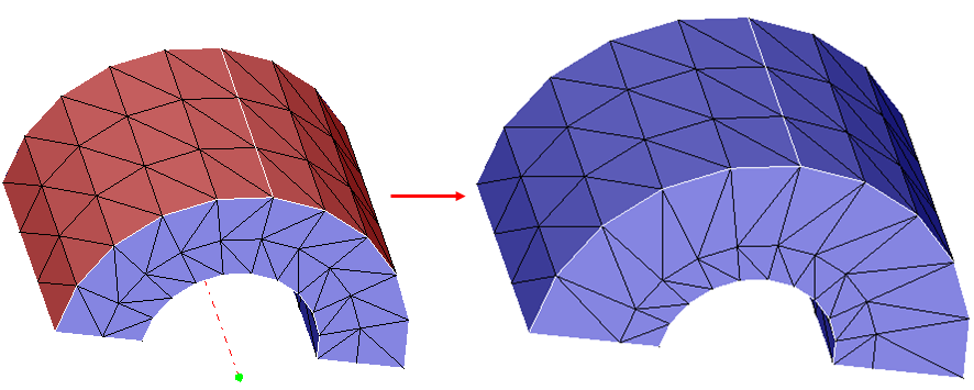 Move mid
nodes with reference to corner nodes
Move mid
nodes with reference to corner nodesThis option is used to adjust the mid-nodes based on the corner nodes position. The input can be bodies or faces or edges.
Example : In the below example, mid-nodes are adjusted with reference to the corner nodes and the defined axis.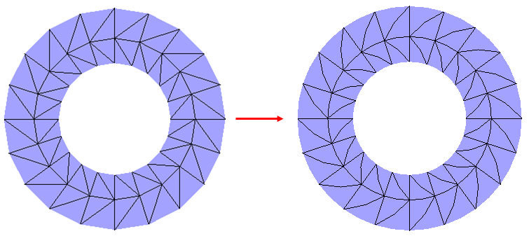
To Surface
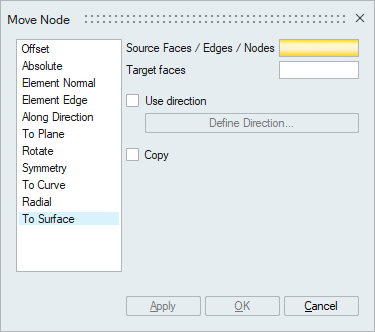
This is used to project nodes on to the target faces. The input can be faces/edges/nodes.
Use direction
You can use this option to define the direction of projection.
Copy
Turn this toggle ON to create only orphan nodes at the new position.
Example