Join
![]()
Description
Join provides an easy and automated way of creating matching mesh between components in an FE model. The user can either select the bodies or faces and do join. It does not support CAD model.
- Show
The overlapping faces can be viewed using this button.
- Join
This is used to join the bodies/faces.
- Tolerance
Gap distance to identify the overlapping faces. Increase in tolerance value will identify more number of overlapping faces.
- Local re-mesh
Re-meshes the assembled faces and its adjacent faces automatically.
Note:Local re-mesh is disabled for option since the mesh is not modified during the process.
Cylinder
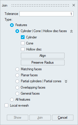
This is used to join the overlapping cylindrical faces in the model.
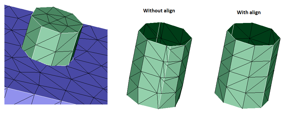
- Align
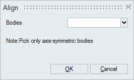
This is used to create mapped mesh on the shared faces. This will pop up a dialog where the user can select axi-symmetric bodies like bolts, valve-seats, valve guides and etc.
- Preserve Radius
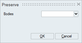
This will pop-up a dialog where the user can select bodies whose radius has to be preserved during join.
- Meshing Parameters
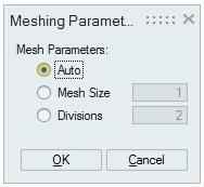
This dialog will show up when Join button is clicked. The mesh on the shared face can be decided using the following options.
- Auto - Average element edge length is used as mesh size.
- Mesh Size - User defined mesh size.
- Divisions - Number of layers along axial direction.
Cone
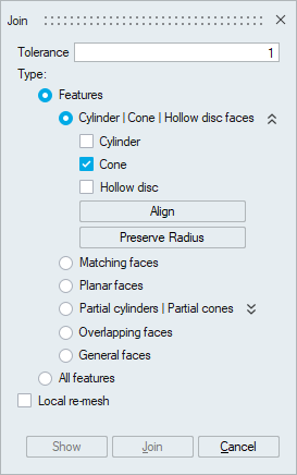
This is used to join overlapping conical faces in the model.
- Align
This will create mapped mesh on the shared face. Only axi-symmetric bodies can be selected.
- Preserve Radius
Select the bodies whose radius to be preserved.
- Meshing Parameters
The mesh on the shared face can be controlled using this option. This dialog will show up during join.
- Auto - Average element edge length is used as mesh size.
- Mesh Size - User defined mesh size.
- Divisions - Number of layers along axial direction.
Hollow disc
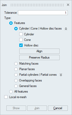
This is used to join the overlapping hollow disc faces in the model.
- Align
This is used to create mapped mesh on the shared faces. This will pop up a dialog where the user can select axi-symmetric bodies like valve-seats, etc.
- Preserve Radius
This will pop-up a dialog where the user can select bodies whose radius has to be preserved during join.
- Meshing Parameters
This dialog will show up when Join button is clicked. The mesh on the shared face can be decided using the following options.
- Auto - Average element edge length is used as mesh size.
- Mesh Size - User defined mesh size.
- Divisions - Number of layers along axial direction.
Matching faces
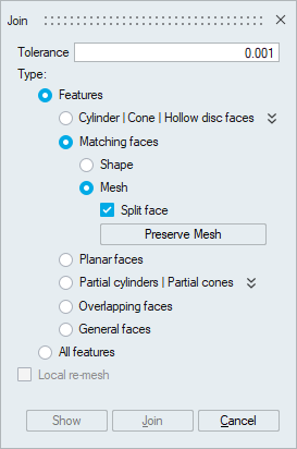
- Shape
Faces having non-identical mesh but identical geometry(shape) can be joined using this option.
- Mesh
Faces having identical mesh and identical geometry can be joined using this option.
- Split face
Use this toggle to join faces having identical mesh locally at few regions.
- Preserve Mesh
Select the bodies whose mesh have to be preserved.
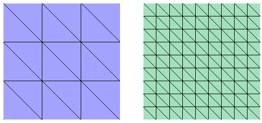
Planar faces
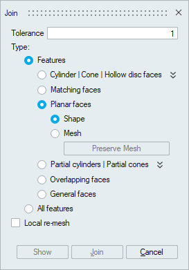
This is used to join overlapping planar faces in the model. Supported for planar faces containing Tri and/or Quad elements.
- Shape
The mesh on both the faces will be modified.
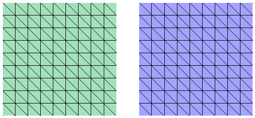
- Mesh
The mesh on one face will preserved as much as possible.
- Preserve Mesh
Select the bodies whose mesh have to be preserved.
Partial cylinders
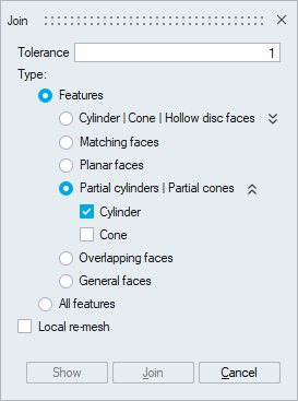
This is used to join overlapping partial cylinders in the model.
Partial cones
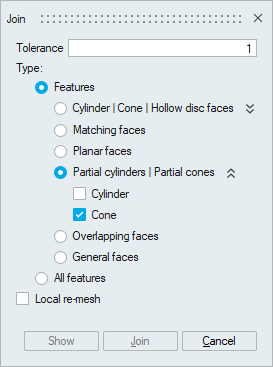
This is used to join overlapping partial conical faces in the model.
Overlapping faces
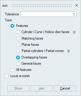
This option joins all overlapping faces in one shot. It uses a new algorithm to do the join process.
General faces
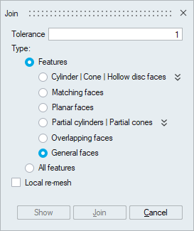
This is used to join faces of any kind of geometry.
All features
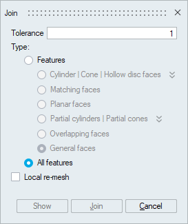
It provides an automated way to identify and join all kind of overlapping faces.