Property
![]()
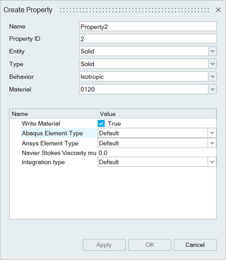
This tool is used to define properties for Solids, Fluids, Shells, Beam, Bar and Rigid Elements. The parameters of the property dialog will be displayed based on the defined solutions.
| Entity | Type | Behavior |
|---|---|---|
| Solid | Solid | Isotropic, Orthotropic, Gasket, Acoustic, AnIsotropic, Cohesive, Continuum Shell Composite |
| Fluid | ||
| Shell | Shell | Isotropic, Composite |
| Membrane | Isotropic | |
| Rigid Body | ||
| Plotel | ||
| Axisymmetric | ||
| Acoustic | Infinite, Adaptive Layer, Absorber | |
| Plane Strain | ||
| Surface | ||
| Plane Stress | ||
| Bar | Bar | |
| Beam | ||
| Truss | ||
| Advanced | ||
| Rigid Body | ||
| Rigid Bar | Rbe2 | |
| Rbe3 | ||
Description
Property dialog is used to define following
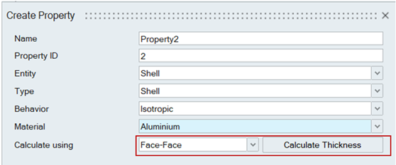
- Thickness for shell elements.
- The thickness of the shell can be computed, from the solid body by
selecting the appropriate method (face-face, face-node,
element-node, node-node) in the Calculate using option and clicking
the Calculate button.
- The thickness of the shell can be computed, from the solid body by
selecting the appropriate method (face-face, face-node,
element-node, node-node) in the Calculate using option and clicking
the Calculate button.
- Section properties for bar and beam elements.
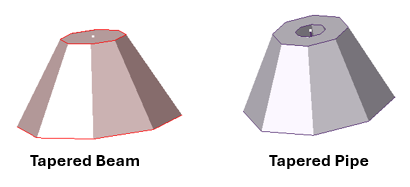
- The section of bar and beam elements can be viewed by selecting the
respective bodies in model tree. Visualization is supported for
rectangle, circle and hollow circle, C, T, L, Plus, I, Tapered Beam
and Tapered Pipe cross sections only.
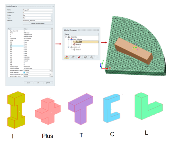
- If the local coordinate system (Sys_Coord_ID) is referred in property, bar and beam section will orient as per the Y and Z axis of the local coordinate system.
- The bar and beam section orientations can be viewed based on the required solver type by using the Beam section orientation option in the preference dialog.
- The section of bar and beam elements can be viewed by selecting the
respective bodies in model tree. Visualization is supported for
rectangle, circle and hollow circle, C, T, L, Plus, I, Tapered Beam
and Tapered Pipe cross sections only.
- Element types for Solid, Gasket and Shell elements.
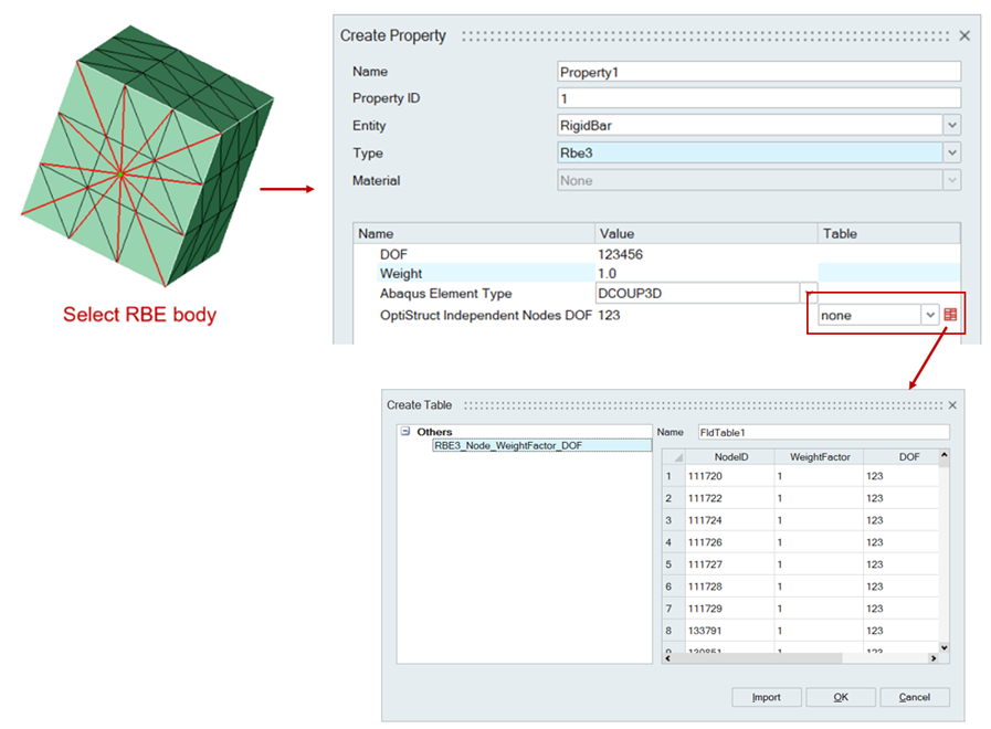
- Element types and DOF of the RBE's.
- The RBE3 independent nodes can be defined with individual DOF and
weight factor. This is supported only for OptiStruct solver input
file export.
- The RBE3 independent nodes can be defined with individual DOF and
weight factor. This is supported only for OptiStruct solver input
file export.