Material Orientation
![]()
Material properties such as Young's modulus, Poisson's ratio, and thermal expansion coefficients, thermal conductivity are key factors that influence how a material behaves under various loading conditions.
Material orientation helps users define the orientation for materials which have distinct material properties along different axes due to the arrangement of fibers or layers within the material.
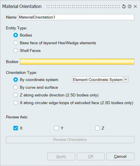
- Bodies: Solid/Shell bodies can be given as input to modify material orientation.
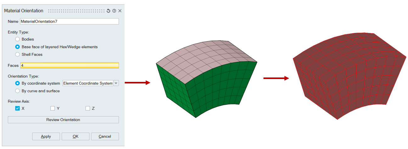
- Base face for layered Hex/Wedge elements: Layered elements connected to
selected faces will be considered for Material orientation as shown
below.
- Shell faces: Select shell faces of shell bodies.
Users can review the material orientation for each element for given entities using “Review Orientation”.
Review convections:
- Material X-axis: Red
- Material Y-axis: Green
- Material Z-axis: Blue
- Coordinate system:
Select the coordinate system that must be used as material orientation for selected entities. In addition to coordinate systems, engineers can specify “Element coordinate system” as material orientation.
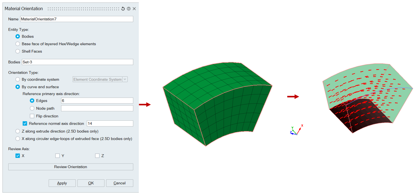
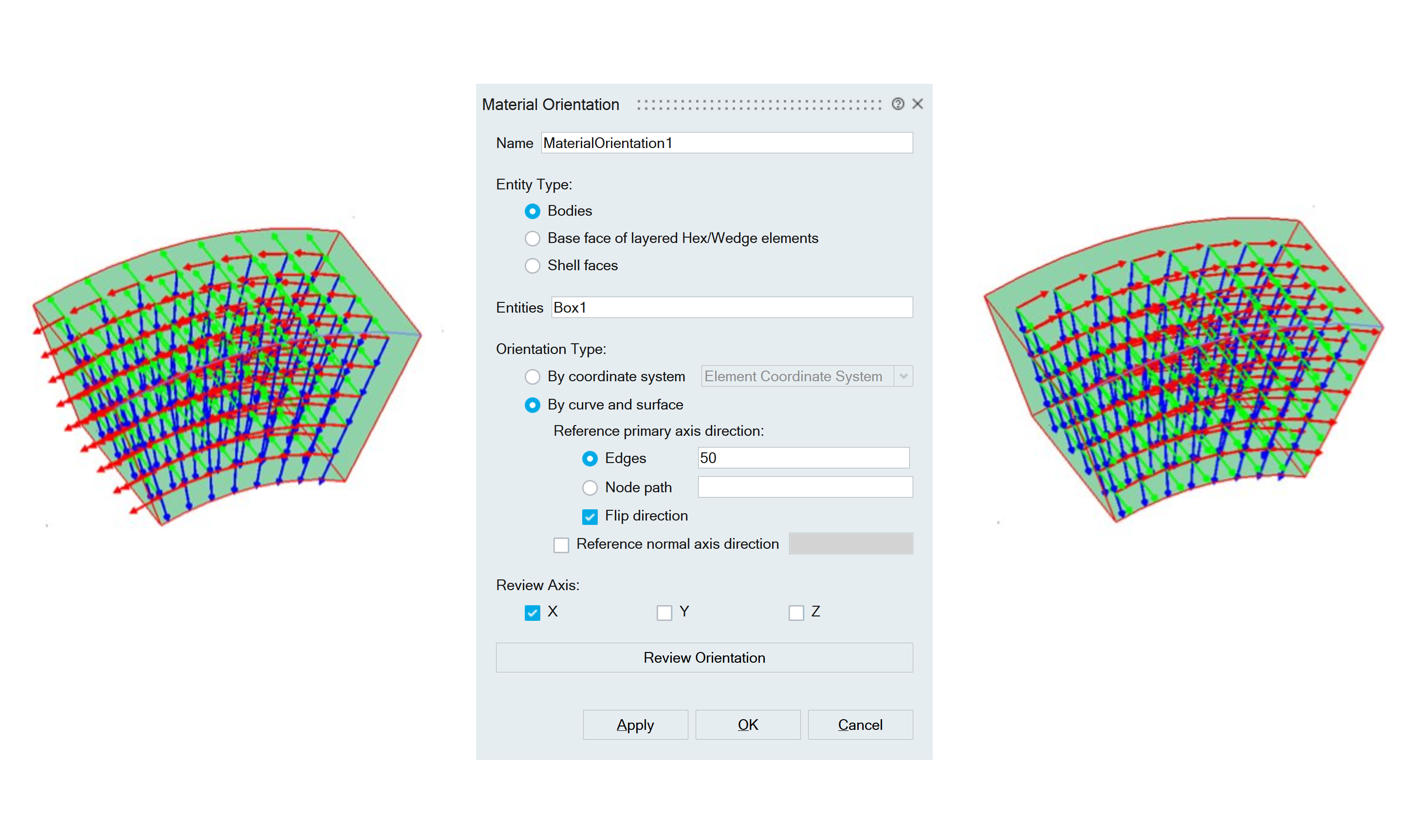
- Curve and surface:Reference primary axis direction:
- Select reference edges/node path to find the primary axis direction for each element in selected entities.
- For each element in selected entities, the closest point on edge
will be found and use the edge tangent as reference primary
direction for that element.
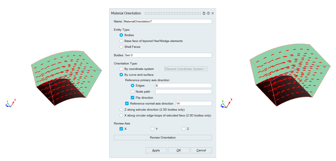
- Users can flip the primary axis direction using “Flip direction”
check box as shown below.
Reference normal axis direction:- Select reference faces to find the normal axis direction for each element in selected entities.
- For each element in selected entities, the closest point on
reference face will be found and normal at this point will be
used as reference normal axis direction for that
element.
 Z along extrude direction :
- Using this option, we can create material orientation automatically for 2.5D bodies specifically for sheet metal applications.
- From the selected bodies, 2.5D bodies will be filtered and the top faces will be extracted and used as reference normal direction for each element present.
- From the selected bodies, 2.5D bodies will be filtered and the top faces will be extracted and used as reference normal direction for each element present.
- Supported only for “Bodies” entity type.
X along circular edge loops of extruded face:- Using this option, we can create material orientation automatically for 2.5D bodies, having edge loops
- All edge loops from respective 2.5D body will be extracted to find X direction and the top face extracted will be considered for Z direction.
- Y direction is obtained by cross product of two vectors.
- Supported only for “Bodies” entity type.
Users can swap X and Y direction using “Swap X and Y”.
Review Axis:
Users can review the computed material coordinate system axes by selecting the corresponding checkboxes.
Solver entry information:
| Solver | Solver entry |
|---|---|
| OptiStruct | Respective element blocks in CTRIA3, CTRIA6, CQUAD4, CQUAD8, CTETRA, CHEXA, CPENTA, CPYRA |
| Abaqus |
*DISTRIBUTION, *DISTRIBUTION TABLE - COORD3D |