Common limitations of the FluxMotor solution
Thermal considerations for FluxMotor
Parts created in SimLab can be utilized in FluxMotor for thermal
simulations using an equivalent thermal network approach. To ensure accurate
results, users should consider subdividing their parts into smaller bodies that meet
the following conditions:
- Temperature Uniformity: The temperature within each body (corresponding to a thermal node) should closely match the mean temperature of the body.
- Heat Transfer Direction: Heat flow within a body must primarily occur in identifiable directions, ideally aligning with other nodes.
- Node Isolation: A body representing one thermal node must not
completely enclose another node. Please see the example below.
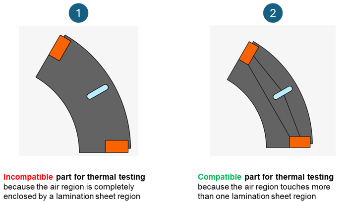
The goal is to create thermal nodes where each node exhibits consistent thermal behavior and experiences similar thermal phenomena.
- Accuracy vs. Complexity: Increasing the number of thermal nodes improves accuracy but can resemble solving a finite element model. By focusing on key physical areas of the motor (e.g., winding, tooth, magnet), the number of nodes can be reduced while maintaining high-quality results.
Here below is an example of a thermal network describing an electric motor in FluxMotor:
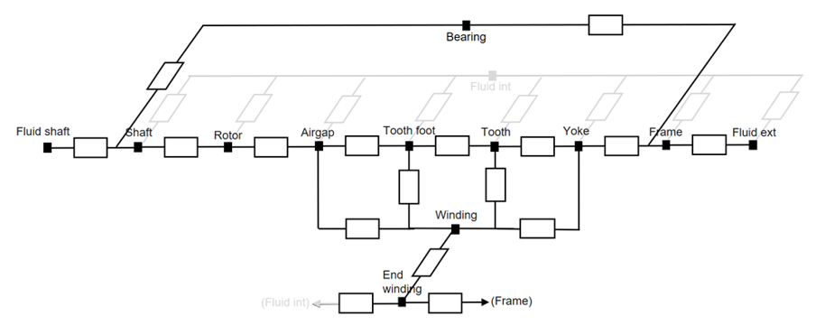
In FluxMotor's thermal solver, the motor is modeled as an
equivalent circuit comprising thermal resistances and nodes:
- Nodes represent distinct regions (e.g., winding, tooth foot, magnet) with specific thermal properties.
- Resistance represents heat transfer paths between nodes.
- The current through a resistance signifies heat transfer, while the voltage drop corresponds to the temperature difference between nodes.
This simple mesh-based approach effectively captures the motor's thermal dynamics for analysis and optimization.