Screw2
Analyze the board to prevent damage.
More detailed information:
- Screw Definition
- Component Group
- Component Group: Select a component group for screw assignment.
- Measure Base: Select a measurement base.
- Via Size: Recognize the specified via as a screw.
- Pad Shape: Set the clearance measurement based on the pad shape of the screw.
- Hole Shape: Set the clearance measurement based on the hole shape of the screw.
- Hole Center: Set the clearance measurement based on the hole center of the screw.
- Board Figure: Recognize the board figure as a screw.
- Padstack: Set the padstack using a string filter. Use this
when the screw was designed with the board figure pad.
- Pad Shape: Set the clearance measurement based on the pad shape of the screw.
- Hole Shape: Set the clearance measurement based on the hole shape of the screw.
- Hole Center: Set the clearance measurement based on the hole center of the screw.
- Figure Diameter: Recognize an object designed with Figure
hole using the hole size as the screw.
- Hole Shape: Set the clearance measurement based on the hole shape of the screw.
- Hole Center: Set the clearance measurement based on the hole center of the screw.
- Padstack: Set the padstack using a string filter. Use this
when the screw was designed with the board figure pad.
- Component Group
- Silt Definition
- Distance to slit area from a screw measure base: Define an area to find a slit hole.
- Silt Layer: Select a layer that is drawn in the slit hole.
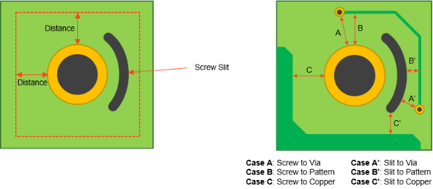
Figure 1. - Checking
- Recognize Selected Component’s Placed Side as Top: Recognize the component placed layer as the top layer.
- Clearance to Component
- Item: Specify the item name.
- Component Group: Select the component group for analysis.
- Measure Base: Select a measurement base.
- Screw: Select a screw for analysis.
- Screw Measure Base: Select a measurement base for the screw.
- Top Clearance: Set the clearance between the screws and components placed on the top layer.
- Bottom Clearance: Set the clearance between the screws and components placed on the top layer.
- Remainder: Set the clearance for the remainder.
- Item: Specify the item name.
- Component Measure Base: Select a measurement base.
- Screw: Select a screw for analysis.
- Screw Measure Base: Select a measurement base for the screw.
- Top Clearance: Set the clearance for the analysis between the screws and components placed on the top layer.
- Bottom Clearance: Set the clearance for the analysis between the screws and components placed on the top layer.
- Except for SMD Pins, not having Metal-Mask: Exclude the SMD component’s pin that does not have metal mask data.
- Clearance to Via: Set the clearance between the screw and via for
the top, bottom, and inner layer.
- Item: Specify the item name.
- Screw: Select a screw for analysis.
- Screw Measure Base: Select a measurement base for the screw.
- Target: Select a target object for analysis among Screw, Slit, and Screw+Slit.
- Top Clearance: Set the clearance between the screws and vias on the top layer.
- Inner Clearance: Set the clearance between the screws and vias on the inner layer.
- Bottom Clearance: Set the clearance between the screws and vias on the bottom layer.
- Clearance to Pattern: Set the clearance between the screw and
pattern for the top, bottom, and inner layer.
- Item: Specify the item name.
- Screw: Select a screw for analysis.
- Screw Measure Base: Select a measurement base for the screw.
- Target: Select a target object for analysis among Screw, Slit, and Screw+Slit.
- Top Clearance: Set the clearance between the screws and route patterns on the top layer
- Inner Clearance: Set the clearance between the screws and route patterns on the inner layer.
- Bottom Clearance: Set the clearance between the screws and route patterns on the bottom layer.
- Except Net Segments under Pad Area: Exclude a nets existence in the component pad area during analysis.
- Clearance to Copper: Set the clearance between the screw and
copper-pour for the top, bottom, and inner layer.
- Item: Specify the item name.
- Screw: Select a screw for analysis.
- Screw Measure Base: Select a measurement base for the screw.
- Target: Select a target object for analysis among Screw, Slit, and Screw+Slit.
- Top Clearance: Set the clearance between the screws and copper polygons on the top layer.
- Inner Clearance: Set the clearance between the screws and copper polygons on the inner layer.
- Bottom Clearance: Set the clearance between the screws and copper polygons on the bottom layer.
- Exclude Ground Net: Exclude the ground net from analysis by using the string filter.
- Exclude Same Net: Exclude nets connected to the screw from the analysis.
- Slit existence check: Check the existence of slits around the screws that are inspected.