
/MAT/LAW88
Block Format Keyword This law represents the behavior of a hyperelastic material with strain rate effects. This law is generally used to model incompressible rubbers, polymers, foams, and elastomers. It is defined by a family of stress versus strain curves at different strain rates.
Unloading can be represented using an unloading function or by providing hysteresis and shape factor inputs to a damage model based on energy. This law is only compatible with solid elements.
Format
| (1) | (2) | (3) | (4) | (5) | (6) | (7) | (8) | (9) | (10) |
|---|---|---|---|---|---|---|---|---|---|
| /MAT/LAW88/mat_ID/unit_ID | |||||||||
| mat_title | |||||||||
| K | Fcut | Fsmooth | NL | ||||||
| fct_IDunL | FscaleunL | Hys | Shape | Tension | |||||
| (1) | (2) | (3) | (4) | (5) | (6) | (7) | (8) | (9) | (10) |
|---|---|---|---|---|---|---|---|---|---|
| fct_IDLi | FscaleLi | ||||||||
Definition
| Field | Contents | SI Unit Example |
|---|---|---|
| mat_ID | Material identifier. (Integer, maximum 10 digits) |
|
| unit_ID | (Optional) Unit identifier. (Integer, maximum 10 digits) |
|
| mat_title | Material title. (Character, maximum 100 characters) |
|
| Initial density. (Real) |
||
| Poisson ratio. For incompressible materials 0.495 is maximum value. Default = 0.495 (Real) |
||
| K | Bulk modulus. (Real) |
|
| Fcut | Cutoff frequency for strain rate
filtering. Default = 1030 (Real) |
|
| Fsmooth | Smooth strain rate option flag.
(Integer) |
|
| NL | Number of loading stress strain
curve. (Integer) |
|
| fctunL | Unloading engineering stress versus
engineering strain function identifier. 3 (Integer) |
|
| FscaleunL | Unloading function scale
factor. Default = 1.0 (Real) |
|
| Hys | Hysteresis unloading factor. Ignore if,
unloading function is used. 3 0.0 ≤ Hys ≤ 1.0 Default = 0.0 (Real) |
|
| Shape | Shape factor. Ignored if, unloading
function is used. 3 Default = 1.0 (Real) |
|
| Tension | Unloading rate effects option flag.
4
(Integer) |
|
| fct_IDLi | Loading function identifier defining
engineering stress versus engineering strain for ith strain rate
function. (Integer) |
|
| Strain rate for ith loading
engineering stress versus engineering strain function. (Real) |
||
| FscaleLi | Scale factor for ith loading
function. Default = 1.0 (Real) |
Example (Rubber)
#RADIOSS STARTER
#---1----|----2----|----3----|----4----|----5----|----6----|----7----|----8----|----9----|---10----|
/UNIT/1
unit for mat
Mg mm s
#---1----|----2----|----3----|----4----|----5----|----6----|----7----|----8----|----9----|---10----|
#- 1. MATERIALS:
#---1----|----2----|----3----|----4----|----5----|----6----|----7----|----8----|----9----|---10----|
/MAT/LAW88/1/1
Sample rubber
# RHO_I
1.552E-9
# NU K F_CUT F_SMOOTH NL
.495 300 0 0 1
#FCT_ID_UN F_SCALE_UN HYS SHAPE TENSION
0 0 0 0 0
#FCT_ID_LI F_SCALE_LI EPSI_LI
1 .0 0
#---1----|----2----|----3----|----4----|----5----|----6----|----7----|----8----|----9----|---10----|
#- 2. FUNCTIONS:
#---1----|----2----|----3----|----4----|----5----|----6----|----7----|----8----|----9----|---10----|
/FUNCT/1
Sample rubber
# X Y
-0.96 -50275.7077778
-0.95 -23497.9100000
-0.94 -12886.7788889
-0.93 -7843.6749887
-0.92 -5138.1561224
-0.91 -3554.9287654
-0.9 -2565.7112346
-0.89 -1915.1453719
-0.88 -1469.3035170
-0.87 -1153.2398093
-0.86 -922.7390569
-0.85 -750.5444671
-0.84 -619.2177778
-0.83 -517.2417993
-0.82 -436.7973365
-0.81 -372.4461828
-0.8 -320.3246814
-0.79 -277.6353515
-0.78 -242.3180370
-0.77 -212.8322259
-0.76 -188.0099412
-0.75 -166.9544444
-0.74 -148.9692899
-0.73 -133.5078568
-0.72 -120.1369349
-0.71 -108.5101039
-0.7 -98.3480367
-0.69 -89.4237611
-0.68 -81.5515166
-0.67 -74.5782484
-0.66 -68.3770544
-0.65 -62.8420952
-0.64 -57.8846082
-0.63 -53.4297634
-0.62 -49.4141654
-0.61 -45.7838564
-0.6 -42.4927087
-0.59 -39.5011243
-0.58 -36.7749754
-0.57 -34.2847385
-0.56 -32.0047815
-0.55 -29.9127752
-0.54 -27.9892042
-0.53 -26.2169594
-0.52 -24.5809969
-0.51 -23.0680513
-0.5 -21.6663932
-0.49 -20.3656248
-0.48 -19.1565054
-0.47 -18.0308033
-0.46 -16.9811681
-0.45 -16.0010225
-0.44 -15.0844679
-0.43 -14.2262038
-0.42 -13.4214576
-0.41 -12.6659240
-0.4 -11.9557116
-0.39 -11.2872976
-0.38 -10.6574867
-0.37 -10.0633764
-0.36 -9.5023254
-0.35 -8.9719268
-0.34 -8.4699838
-0.33 -7.9944885
-0.32 -7.5436030
-0.31 -7.1156428
-0.3 -6.7090617
-0.29 -6.3224389
-0.28 -5.9544671
-0.27 -5.6039420
-0.26 -5.2697526
-0.25 -4.9508733
-0.24 -4.6463558
-0.23 -4.3553226
-0.22 -4.0769607
-0.21 -3.8105162
-0.2 -3.5552892
-0.19 -3.3106295
-0.18 -3.0759321
-0.17 -2.8506340
-0.16 -2.6342104
-0.15 -2.4261720
-0.14 -2.2260620
-0.13 -2.0334536
-0.12 -1.8479479
-0.11 -1.6691715
-0.1 -1.4967748
-0.09 -1.3304300
-0.08 -1.1698299
-0.07 -1.0146860
-0.06 -0.8647273
-0.05 -0.7196992
-0.04 -0.5793621
-0.03 -0.4434907
-0.02 -0.3118725
-0.01 -0.1843075
0 0
0.01 0.0594069
0.02 0.1759026
0.03 0.2890387
0.04 0.3989654
0.05 0.5058247
0.06 0.6097510
0.07 0.7108714
0.08 0.8093065
0.09 0.9051706
0.1 0.9985721
0.11 1.0896136
0.12 1.1783928
0.13 1.2650025
0.14 1.3495306
0.15 1.4320609
0.16 1.5126730
0.17 1.5914428
0.18 1.6684424
0.19 1.7437404
0.2 1.8174023
0.21 1.8894906
0.22 1.9600648
0.23 2.0291815
0.24 2.0968950
0.25 2.1632570
0.26 2.2283170
0.27 2.2921220
0.28 2.3547173
0.29 2.4161460
0.3 2.4764493
0.31 2.5356667
0.32 2.5938361
0.33 2.6509937
0.34 2.7071741
0.35 2.7624105
0.36 2.8167348
0.37 2.8701776
0.38 2.9227681
0.39 2.9745344
0.4 3.0255035
0.41 3.0757013
0.42 3.1251527
0.43 3.1738816
0.44 3.2219109
0.45 3.2692626
0.46 3.3159581
0.47 3.3620177
0.48 3.4074610
0.49 3.4523070
0.5 3.4965738
0.51 3.5402789
0.52 3.5834392
0.53 3.6260709
0.54 3.6681897
0.55 3.7098107
0.56 3.7509483
0.57 3.7916167
0.58 3.8318294
0.59 3.8715993
0.6 3.9109391
0.61 3.9498610
0.62 3.9883767
0.63 4.0264974
0.64 4.0642342
0.65 4.1015977
0.66 4.1385979
0.67 4.1752449
0.68 4.2115482
0.69 4.2475169
0.7 4.2831600
0.71 4.3184862
0.72 4.3535038
0.73 4.3882209
0.74 4.4226452
0.75 4.4567845
0.76 4.4906460
0.77 4.5242368
0.78 4.5575638
0.79 4.5906337
0.8 4.6234529
0.81 4.6560277
0.82 4.6883642
0.83 4.7204682
0.84 4.7523455
0.85 4.7840015
0.86 4.8154417
0.87 4.8466713
0.88 4.8776953
0.89 4.9085187
0.9 4.9391461
0.91 4.9695823
0.92 4.9998316
0.93 5.0298985
0.94 5.0597872
0.95 5.0895019
0.96 5.1190464
0.97 5.1484248
0.98 5.1776407
0.99 5.2066979
1 5.2355999
1.01 5.2643501
1.02 5.2929521
1.03 5.3214090
1.04 5.3497240
1.05 5.3779003
1.06 5.4059409
1.07 5.4338486
1.08 5.4616265
1.09 5.4892772
1.1 5.5168035
1.11 5.5442081
1.12 5.5714934
1.13 5.5986620
1.14 5.6257164
1.15 5.6526590
1.16 5.6794920
1.17 5.7062177
1.18 5.7328383
1.19 5.7593560
1.2 5.7857728
1.21 5.8120909
1.22 5.8383121
1.23 5.8644385
1.24 5.8904718
1.25 5.9164141
1.26 5.9422670
1.27 5.9680323
1.28 5.9937118
1.29 6.0193071
1.3 6.0448199
1.31 6.0702516
1.32 6.0956040
1.33 6.1208785
1.34 6.1460766
1.35 6.1711998
1.36 6.1962494
1.37 6.2212269
1.38 6.2461336
1.39 6.2709708
1.4 6.2957398
1.41 6.3204418
1.42 6.3450782
1.43 6.3696501
1.44 6.3941586
1.45 6.4186050
1.46 6.4429903
1.47 6.4673157
1.48 6.4915822
1.49 6.5157909
1.5 6.5399427
1.51 6.5640388
1.52 6.5880801
1.53 6.6120675
1.54 6.6360020
1.55 6.6598846
1.56 6.6837160
1.57 6.7074973
1.58 6.7312292
1.59 6.7549126
1.6 6.7785483
1.61 6.8021372
1.62 6.8256800
1.63 6.8491775
1.64 6.8726305
1.65 6.8960397
1.66 6.9194058
1.67 6.9427296
1.68 6.9660118
1.69 6.9892530
1.7 7.0124539
1.71 7.0356151
1.72 7.0587374
1.73 7.0818213
1.74 7.1048675
1.75 7.1278766
1.76 7.1508491
1.77 7.1737857
1.78 7.1966869
1.79 7.2195532
1.8 7.2423853
1.81 7.2651837
1.82 7.2879488
1.83 7.3106813
1.84 7.3333816
1.85 7.3560502
1.86 7.3786876
1.87 7.4012943
1.88 7.4238707
1.89 7.4464174
1.9 7.4689347
1.91 7.4914231
1.92 7.5138831
1.93 7.5363151
1.94 7.5587194
1.95 7.5810966
1.96 7.6034470
1.97 7.6257710
1.98 7.6480690
1.99 7.6703413
2 7.6925885
4 11.8937916
#---1----|----2----|----3----|----4----|----5----|----6----|----7----|----8----|----9----|---10----|
#enddata
/END
#---1----|----2----|----3----|----4----|----5----|----6----|----7----|----8----|----9----|---10----|Comments
- This model utilizes an Ogden material formulation. Material parameters are directly derived from the input stress strain curves from uniaxial tests for different strain rates. The material is assumed to be nearly incompressible with Poisson’s ratio = 0.495.
- Strain rate effects can be modeled by
including loading engineering stress strain test data at different strain rates
fct_IDLi. This can be easier than
calculating viscous parameters for traditional hyperelastic material models. When using
stress strain curves at different strain rates, the following suggestions are
recommended:
- The stress strain curve should be monotonic increasing and smooth. The derivative of the stress strain curve should be smooth.
- Enable strain rate smoothing by defining, Fsmooth =1 with Fcut =500 Hz.
- Unloading can be represented using an unloading
function, fct_IDunL, or by providing
hysteresis, Hys,
and shape factor, Shape.
Otherwise, the first loading curve
fct_IDLi is used as an unloading
function.
When using the hysteresis parameters, the loading curves are used for both loading and unloading and the unloading stress tensor is reduced by:
with
Where,- Current energy
- Maximum energy corresponding to the quasi-static behavior
- The loading and unloading curves are
defined with positive stress and strain in tensile and negative stress and strain in
compression.The following curves are needed according to Tension flag:
Figure 1. 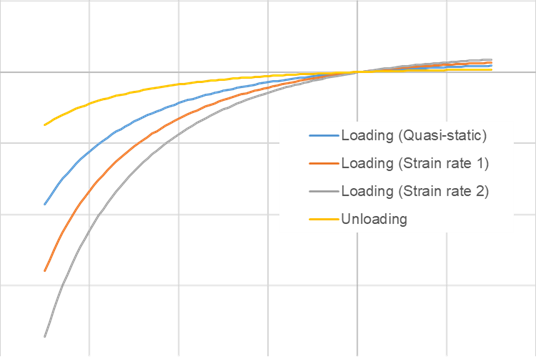
- /VISC/PRONY can be used with this material law to include viscous effects.