Generate and Evaluate a Design Using Topology Optimization
How OptiStruct is used to generate a design for a control arm and how engineering analysis is used to evaluate the design.
The following example illustrates how OptiStruct is used to generate
a design for a control arm and how engineering analysis is used to evaluate the
design.
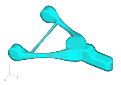
- The package space for the control arm is filled with a finite element mesh.
- Parts of the mesh are designated as
nondesign, and the elements that make up these areas are placed in anondesigncomponent.The darker elements represent attachment points for the frame, shock, spring seat, stabilizer bar, and spindle. Nondesign elements are placed where loads and constraints are applied to the model.Figure 1. Nondesign and Design Space of FEM Model 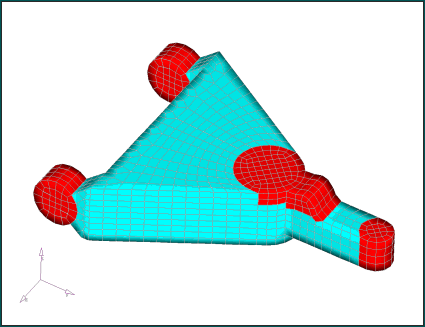
- Loads and constraints are applied to the finite element model.
Three load cases are applied at the spindle and stabilizer bar attachment points.
Constraints are applied at the frame connections and shock point.
The model and parameters are submitted to OptiStruct for topology optimization.
- Elements with material densities below 60% are masked out.
Figure 2. Density Plot of Control Arm with Elements Below 60% Material Density Removed from the Display 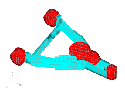
- A finite element model of the control arm using the suggested layout as a
guide is generated.
Figure 3. Finite Element Model of Control Arm Design Based on OptiStruct Results 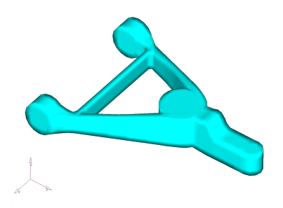
- Stress analysis is performed on the model using the loads and boundary
conditions from the topology optimization run.
Figure 4. Stress Contour Plot of Control Arm Model during Braking Load 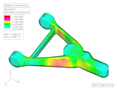
- The performance of the part is evaluated.Subsequent size and shape optimization is performed to minimize the mass while meeting stress and deflection criteria.
Figure 5. Final Design with Shape-optimized Structural Member