
Piezoelectric Analysis
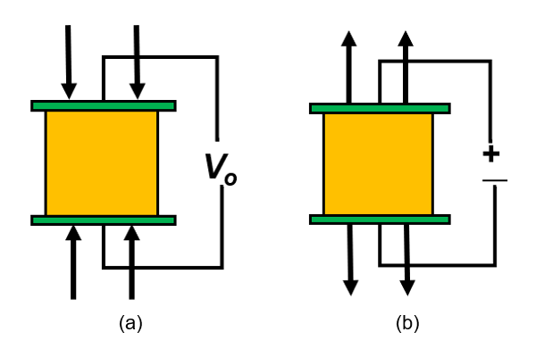
Piezoelectric materials are a class of materials in which structural deformation triggers electrical potential and vice versa.
Piezoelectric Analysis in OptiStruct
Piezoelectric Analysis in OptiStruct involves two-way coupling in which a mechanical excitation will generate an electrical response. Conversely, an electrical excitation will generate a mechanical response. The coupling is strong, which means that both mechanical and electrical responses are solved simultaneously.
Support Information
Piezoelectricity phenomenon is not modeled by a separate analysis type. It is modeled by structural materials, piezoelectric materials, and a coupling definition between the two domains in a structural analysis.
- Linear and Nonlinear Static (SMDISP)
- Normal Modes
- Direct Complex Eigenvalue
- Direct and Modal Frequency Response
- Linear and Nonlinear Transient (SMDISP)
- Element Type
- Order
- Solids
- 1st and 2nd order
Input
Input file entries for piezoelectric coupling definition.
Bulk Data Entries - Material Definitions
- Entry
- Purpose
- MAT1PT
- Defines isotropic permittivity and damping for dielectric materials.
- MAT2PT
- Defines anisotropic permittivity and damping for dielectric materials.
- MATPZO
- Defines the piezoelectric coupling matrix between dielectric and structural components.
- MATT1PT
- Defines a temperature dependent version of MAT1PT.
- MATT2PT
- Defines a temperature dependent version of MAT2PT.
- MATTPZO
- Defines a temperature dependent version of MATPZO.
Bulk Data Entries - Loads, Constraints, and Boundary Conditions
- Entry
- Purpose
- CHARGE
- Defines a point charge.
- CHGAREA
- Defines charge density over an area.
- CHGVOL
- Defines charge density over a volume.
- SPC
- Can be used to define a zero electric potential, by setting C=V.
- SPCD
- Can be used to define a prescribed electric potential, by setting C=V.
- MPC
- Can be used to model an electric conductive surface, by setting C=V.
- TLOAD1/TLOAD2
- Can be used to define a dynamic load.
- When TYPE=LOAD, it can point to CHARGE, CHGARE or CHGVOL
- When TYPE=DISP, it can point to SPCD with C=V
- RLOAD1/RLOAD2
- Can be used to define a dynamic load.
- When TYPE=LOAD, it can point to CHARGE, CHGARE or CHGVOL
- When TYPE=DISP, it can point to SPCD with C=V
Bulk Data Entries - Miscellaneous
- Entry
- Purpose
- PARAM, VAPMTV
- Defines the vacuum permittivity for piezoelectric materials. This is required when relative permittivity is defined in MAT1PT or MAT2PT.
Problem Setup
$ *************************************************************
$ EXAMPLE: LINEAR STATIC ANALYSIS WITH PIEZOELECTRIC COUPLING
$ ************************************************************
DISPLACEMENT = ALL
SPCFORCE = ALL
GPFORCE = ALL
OLOAD = ALL

SUBCASE        1
ANALYSIS STATIC
  SPC =        2
  LOAD =        3
BEGIN BULK
$--1---><---2--><---3--><---4--><--5---><--6---><---7--><--8---><---9-->
PSOLID         1       2
MAT4           2  1000.0
MAT1PT         2  1000.0

CHARGE         3     163             1.0
SPC            2    2890       V     0.0
SPC            2    2875       V     0.0
..
Output
Currently, results are only available in H3D format.
Supported Output Requests
Optimization for Piezoelectric Analysis
- Linear Static Analysis
- DISP, COMP (total and regional)
- Normal Modes Analysis
- FREQ, DISP (mode shape)
- Direct and Modal Frequency Response
- FRDISP, FRVELO, FRACCL