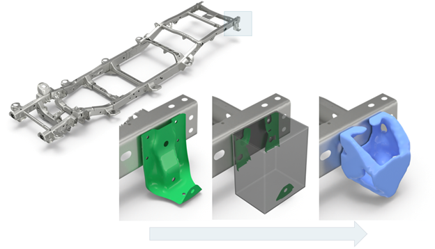
Create Autobox Design Spaces
Autobox will create a voxel design space so that topology optimization can be performed on a part or subsystem.
Additional capabilities include the ability to manage and connect to hard point locations.
-
From the Design Space ribbon, click the
Local tool.
Figure 2. 
-
Click
 on the guide bar to define
the voxel design space size and the RBE3 connection tolerance.
on the guide bar to define
the voxel design space size and the RBE3 connection tolerance.
- Voxel size
- Defines the size of the voxels which will be created.
- RBE3 tolerance
- Will determine spatially which parts and elements to connect to.
- Delete elements not connected to hard points
- Will remove elements of the original selected input that are effectively redundant and should not be included as part of the topology optimization. This options saves having to manually delete any unwanted elements.
- Create new include
- Will organize anything created via the design space process into a new include. DTPL, PSOLID, Component, and so on will be put into the new include.
- Create 2D voxel face elements
- Will create a design space consisting of 2D shell elements only as opposed to 3D voxel elements. The respective PSHELL property and DTPL are created accordingly.
-
For the guide bar, select an input.
A bounding box preview indicating where the design space will be created is displayed in the modeling window.Note: Use the microdialog to move or resize the bounding box. You can also use Autofill to locate the bounding box globally or aligned to the principal axis; depending on the input, one may be better than the other.
Figure 3. 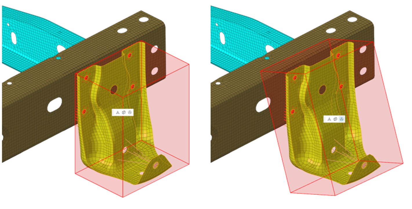
-
Select Connect All.
If Connect All is selected, individual hard points will not be considered and the whole design space will be connected via RBE3s to the initial selected input.
Figure 4. 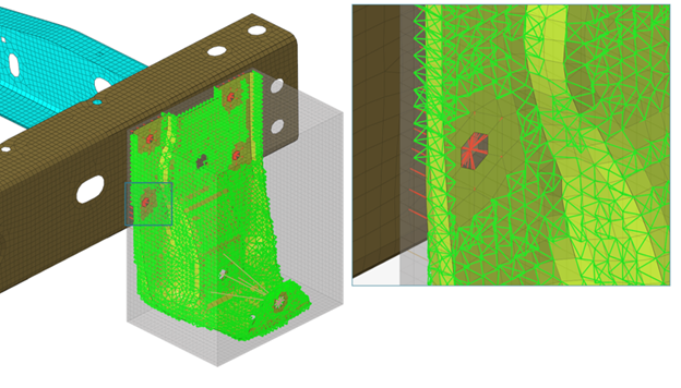
If Connect All is not selected, it is possible to select individual nodes which are defined as hard points and the RBE3 connectivity will connect to the local surrounding elements. The number of rows of connected elements can be controlled, default is two rows. In Figure 5, all five hole hard point locations are selected.
Figure 5. 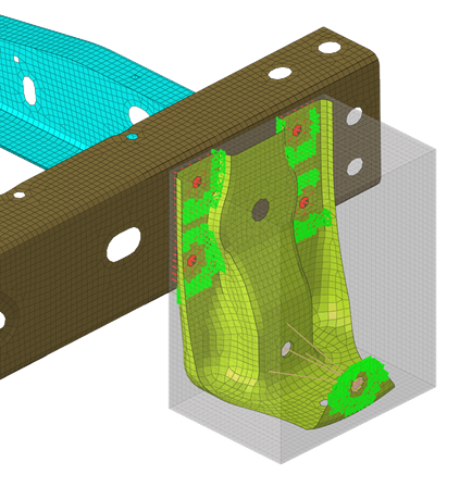
-
On the guide bar, complete one of the following:
- Click
 to apply and stay in the tool.
 - Click
 to apply and close the tool.
 - Click
 to exit the tool without applying.
- Click
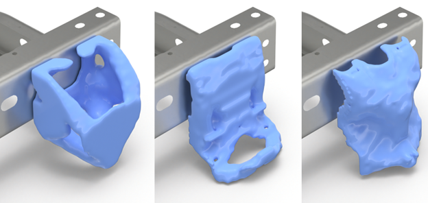
Upon creation, the voxel design space is created along with the design variable (DTPL) and PSOLID property. Once the responses, objectives, and constraints are defined, the topology optimization can be performed.
- Left: full design space, solid with symmetry
- Center: manually reduced design space, solid with symmetry
- Right: full design space, stamp thickness with symmetry