Create Adhesive Design Spaces
Structural adhesives can be very useful for boosting structural stiffness, but they are expensive; hence, determining an optimized quantity and location becomes crucial. Use the Adhesives tool to quickly create OptiStruct optimization run-ready setups that can help to find optimized locations for structural adhesives.
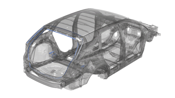
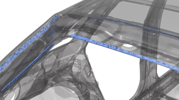
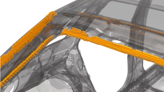
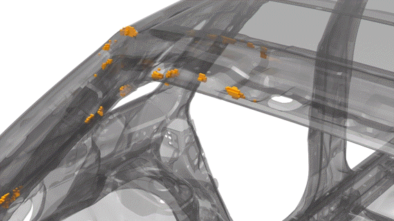
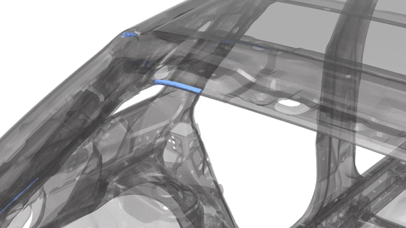
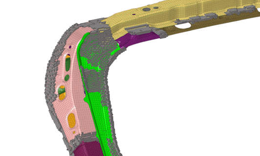
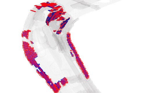
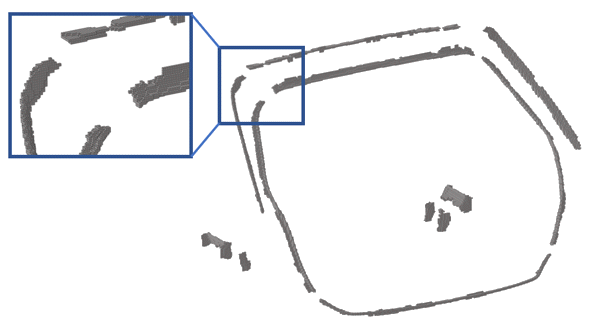
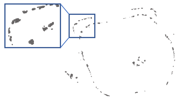
Figure 1 shows a sample automotive model with structural adhesives used to improve stiffness, but the adhesive length is not optimized. Figure 2 shows original adhesive being converted to an Adhesives design space using the process described on this page. Figure 3 and Figure 4 show structural adhesives before and after optimization respectively. The performance of the optimized model shows similar performance benefits, but it saves a significant quantity of adhesives.
The Adhesives tool automatically identifies flange locations from the selected entities. It also creates TIE-based contact between the Adhesives design space (voxels) and the structural elements nearby. It does not add any additional stiffness as it will not create contacts between structural parts. Like Global and Local design spaces, Adhesive design spaces creates a topology design variable.-
From the Design Space ribbon, click the
Adhesives tool.
Figure 6. 
-
Click
 on the guide bar to define
options.
Flange detection:
on the guide bar to define
options.
Flange detection:- Enter a search distance (recommended and default value set to 5).
- Enter a pair angle (recommended and default value set to 30).
Design space:- Enter the Voxel size (default value set to 5).
Tie contact:- Enter a Vicinity tolerance (default value is set to 80% of Voxel size).
- Enter a Reverse angle (recommended and default value set to 30).
-
Select entities.
Available options are Components, Elements, and Parts.
-
Click
 to create the Adhesive design space.
- Assign an appropriate material to the Adhesives design space.
Post-Process Adhesives Design Space Optimization
You can evaluate the performance of appropriate element densities using the following process:
- Import the appropriate element density distribution to the model without any Adhesives design space.
- Extract faces from “faces” using panels/tool.
- Create a Global design space with the extracted faces.
- Use the Tie tool on the Design Space ribbon to connect the newly created design space to the nearby structural elements.
- Submit the analysis.
- Use the Connectors ribbon to create high fidelity adhesives (line connectors with hexa adhesives) if the results meet expectations.