Since version 2026, Flux 3D and Flux PEEC are no longer available.
Please use SimLab to create a new 3D project or to import an existing Flux 3D project.
Please use SimLab to create a new PEEC project (not possible to import an existing Flux PEEC project).
/!\ Documentation updates are in progress – some mentions of 3D may still appear.
SimLab mesh export workflow
Introduction
This section presents the steps to follow in SimLab 2017 to export the mesh in a Nastran file.
Preliminary
Before detailing the workflow to follow, here are some useful information for a first SimLab using:
- In SimLab, contrary to HyperMesh, all the operations (geometry, verifying …) are applied to the mesh and not to the geometry. The CAD import allows only to visualize the geometry. So the first step is to mesh in surface. The volume mesh is done at the end.
- To open the help, press the key « F1 ». The help will be opened on the page concerning the active command.
Workflow
In the following table, the steps to follow in SimLab for a nominal scenario are presented (geometry imported from CAD file, air box creation, etc.).
| Stage | Description | Illustration |
|---|---|---|
| 1 | Open SimLab | |
| 2 |
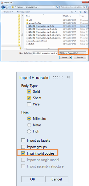
Import the geometry CAD Two CAD imports exist :
Attention: the conversion can generate geometrical
errors.
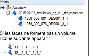
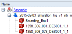
→ For this import, it is truly advised to choose the conversion in Parasolid . It gives access to automatic assembly option « Imprint solid bodies » which has to be checked at the import. After the import, the components are visible in the data tree. If each component faces define a volume, then the following icon appears:
|
CAD through translation :
|
| 3 |
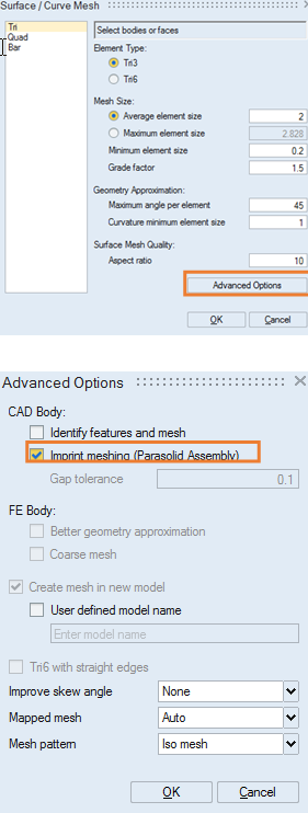
Mesh the geometry faces :
Attention: if the value is too high, the geometry can be
misrepresented
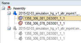
→ The old geometrical components are made invisible, and new component of mesh type are created and visible in the data tree:
All the operations will be applied on those mesh components |
|
| 4 |
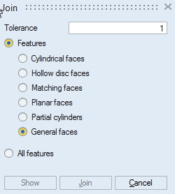
Most of the components which have a contact face will be assembled to obtain a conform mesh, thanks to the option presented before. If there are components which are not assembled, it is possible to do it manually.
Note: If it s a componet indoor another component, use the command «
Boolean »:
|
|
| 5 |
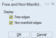
Check the mesh:
In case of defaults, several tools can be used to correct:
|
|
| 6 |
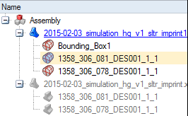
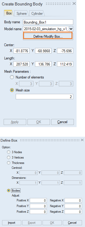
It is possible to create the air box in SimLab or in Flux. If user wants to create the air box in SimLab:
Here we choose « box » shape.
→ A new mesh component « Bounding_Box1 » is created
|
|
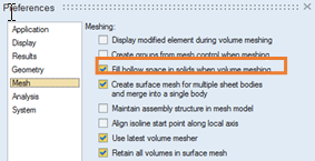
| 7 |
Prepare the project for volume meshing :
→ Only one component exists in the data tree :
|
|
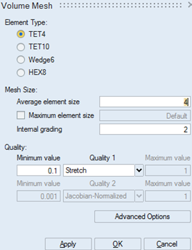
| 8 |
Mesh the component in volume
→ The initial components appear:
|
|
| 9 |
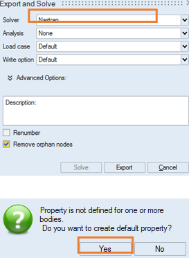
Export the mesh :
Note: the option « Renumber » can be checked if
the file would contain high elements numbers (for example if it is a
little part of a large size device)
|
|