Since version 2026, Flux 3D and Flux PEEC are no longer available.
Please use SimLab to create a new 3D project or to import an existing Flux 3D project.
Please use SimLab to create a new PEEC project (not possible to import an existing Flux PEEC project).
/!\ Documentation updates are in progress – some mentions of 3D may still appear.
HyperMesh (and OptiStruct) mesh export workflow
Introduction
This section presents the steps to follow in HyperMesh (V14.0) to export the mesh in a Nastran file.
Preliminary
Before detailing the workflow to follow, here are some useful information for a first HyperMesh using :
- To displace the geometry in the graphic area, the Ctrl key must be always pressed. To move by translation, use the right click. To move by rotation, make one left click to define the rotation center, then move the mouse with the left click
- To select objects (faces, solids, etc.), make a left click on each object. To unselect objects, make a right click on each object.
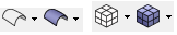
- The transparency of geometry and mesh is managed by the following icons:
To open the help, press the key « F1 ». The help will be opened on the page concerning the active command.
Workflow
In the following table, the steps to follow in HyperMesh for a nominal scenario are presented (geometry imported from CAD file, air box creation, etc.).
| Stage | Description | Illustration |
|---|---|---|
| 1 | Open | |
| 2 | In the « user Profiles » window choose the «Nastran» or «OptiStruct» format and validate the box |
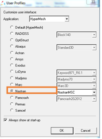
|
| 3 |
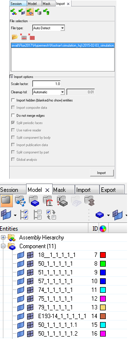
Import the geometry CAD file
→ After the import, the components are visible in the « Model » tab. It is possible to manage the visibility of each component (geometry and mesh) |
|
| 4 |
Make the assembly of the objects in contact to have a conform mesh:
→ The faces in contact become yellow. |
|
| 5 |
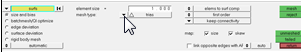
Create the surface mesh :
|
|
| 6 |
It is possible to create the air box in HyperMesh or in Flux. If user wants to create the air box in HyperMesh :
→ The box is automatically assigned to the component created before. |
|
| 7 |
If user has created the air box in HyperMesh (previous step): To manage correctly the air box volume mesh, a Boolean operation of separation has to be applied:
|
|
| 8 |
Mesh in volume :
|
|
| 9 |
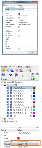
Create the properties and assign to each component :
→ This operation allows identifying the volumes at the import in Flux. |
|
| 10 |
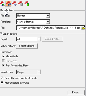
Export the mesh in a Nastran (.bdf,…) or OptiStruct (.fem) file :
|
|