Automatic mode
1. User input parameters
| Label | Symbol | Tooltip, note, formula |
| No. layers | N layers | Number of layers – 1 only |
| No. conductors per layer | N cond | Number of conductors per layer |
| No. parallel paths | P paths | Number of parallel paths (1 or 2) |
| Phase sequence | * | Phase sequence |
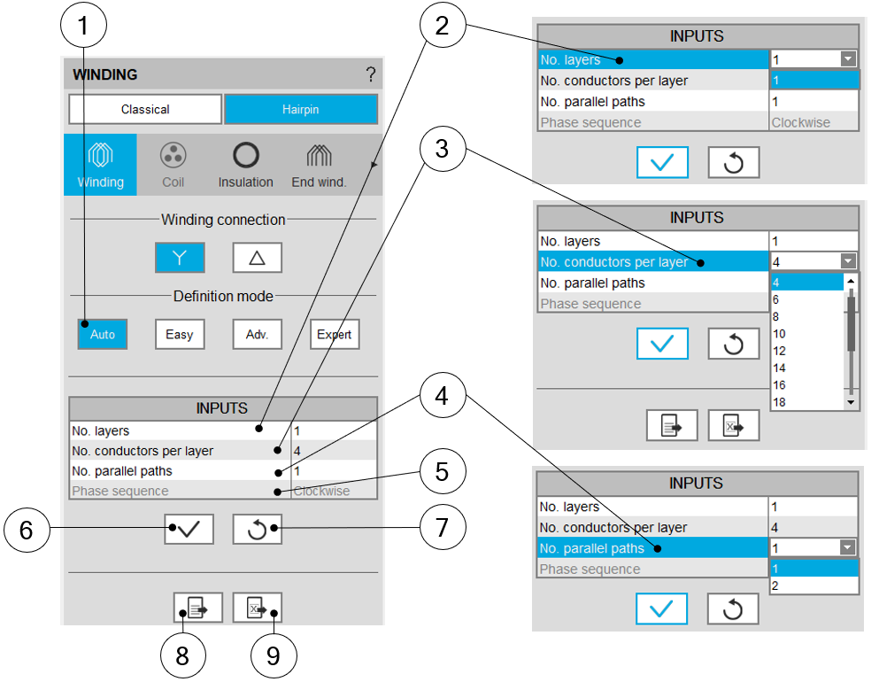
2. Building the winding architecture – Automatic mode – Main principles
 |
|
| Building the winding architecture - Automatic mode | |
| 1 | Selection of Automatic mode for building the winding architecture. |
| 2 | Number of layers - 1 is the only value available for this mode |
| 3 | Number of conductors per layer, must be even and limited to 30. |
| 4 | Number of parallel paths. The possible numbers of parallel paths are
automatically computed and proposed to the user, 2 is the maximum proposed
value according to the used hairpin pattern. When the user chooses a number of parallel paths the connections on the winding scheme are automatically updated. |
| 5 | Definition of the phase sequence i.e. the rotation direction of the
Magneto-Motive Force (M.M.F): Clockwise or Counter clockwise.The rotation direction is defined when facing the machine on the connection side. The phase sequence is set to clockwise and cannot be modified in the current version (grayed field). |
| 6 | Button to apply inputs. Pressing the enter key twice applies inputs too. |
| 7 | Button to restore default input values. Default values are those which define the winding architecture by using the automatic mode. |
| 8 | Icon to export winding data into *.txt or *.xlsx files. |
| 9 | Icon to export hairpin winding connection table into a *.xlsx
file. This file can be shared and reloaded in another working session. |