Tip: To import the skin parts into SimSolid,
ensure the Import Skins option in the geometry import settings is
enabled.
On the Project Tree, click on the Assembly workbench.
On the toolbar, click Create Laminate.
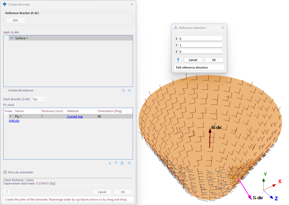
The Create Laminate dialog opens.
Select the skin from the Project Tree or modeling window. Only one skin can be converted to laminate
at once. Exception is applied to instances. Select the Include all
instances checkbox to add and convert all the instances of
selected skin to laminates.
Click Edit to define the reference direction.
The reference direction is in relation to the global coordinate system
(GCS).
Figure 1. A pink arrow indicates the stack direction of the laminate (S-dir) and
a maroon arrow indicates the reference direction which will be used later
for material orientation (R-dir).
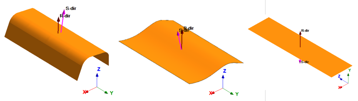
Based on the reference direction, the local-coordinate system for the
material orientation of the ply is aligned in such a way that X-axis is
along the reference direction, Z-axis is always normal to the selected skin
and Y-axis is the cross-product of X-axis and Z-axis.
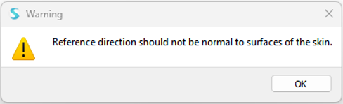
The final reference direction is always obtained by projecting the input
direction on to the skin and it cannot be set normal to the selected skin.
If set, the below warning message should appear. This is applicable for flat
and general skin geometries.
Figure 2. Figure 3. Reference direction cannot be set normal to the skin.
For revolute geometries, the reference direction can be defined with respect
to any of the three global axis directions. However, the recommendation is
to align the reference direction along the revolute geometry.Figure 4. In the case below, the orientation is set to 90o with
respect to the reference direction set along the global
Y-axis.
For stack direction, select from one of the two types:
Top
Stacks the plies along the direction of the reference plane as shown
in graphics.
Bottom
Same as Top but on the other direction of its reference plane.
Click Add ply to manually add plies.
To edit ply definition, double-click in the relevant fields such as name, and
thickness.
To change the material, click on the material hyperlink to open the
Apply material for laminate plies dialog. Select a
material.
Set the orientation angle for each ply.
The orientation angle for the ply would be based on the reference direction
given.
Optional: Rearrange the order of the piles in one of the following ways.
Drag and drop the selected ply.
Click the up or down arrows on the selected ply.
Optional: Click Remove to remove the selected ply from the dialog.
Optional: Click Copy to copy-paste the selection of plies.
Click OK to create the laminate.
Edit Laminates
Edit laminate from the Project Tree
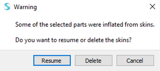
Note: If you delete a laminate, the following warning is posted. Click Resume to retain the skins or select
Delete to delete the skin along with laminate.
To edit the laminate, double-click on the laminate or right-click from the
Project Tree and select
Edit.
The following properties can be edited in the edit mode.
 Create Laminate.
The Create Laminate dialog opens.
Create Laminate.
The Create Laminate dialog opens.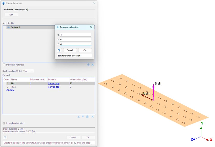
 Remove to remove the selected ply from the dialog.
 Copy to copy-paste the selection of plies.