Rigid Parts
A rigid part is defined as a component that can undergo displacement and rotation under applied loads, but without any internal deformation or strain. Rigid parts behave as a perfectly stiff body where all points maintain their relative positions.
Significance
- Computational efficiency
- Rigid parts are significantly less computationally expensive than deformable parts. By designating components that are much stiffer than their surrounding parts as rigid, you can drastically reduce the number of degrees of freedom in your model, leading to faster analysis times.
- Model simplification
- They allow for the simplification of complex assemblies, especially when dealing with components whose deformation is negligible compared to the overall system's behavior or the deformation of other, more flexible parts.
- Focus on critical areas
- By treating stiff components as rigid, you can direct the computational power towards the areas of your model where deformation and stress are critical and of primary interest.
Typical Applications
Rigid parts are ideal for modeling components that are considerably stiffer than the parts they interact with. Common applications include:
- Fasteners
- Steel bolts, nuts, or rivets connecting plastic components. The deformation of the fastener itself is often negligible compared to the deformation of the softer parts.
- Fixtures and supports
- Stiff structural elements that are intended to provide support but whose own deformation is not of interest.
- Loading plates/pads
- When applying a distributed load through a stiff plate to a more flexible structure, the plate can often be modeled as rigid.
- Symmetry planes/boundary conditions
- In some cases, a rigid part can be used to enforce specific displacement or rotational boundary conditions.
Important Considerations
- Material properties ignored
- When a part is designated as rigid, SimSolid disregards any material properties (for example, Young's Modulus, Poisson's Ratio) previously assigned to it. Its behavior is solely governed by its rigid body kinematics. Only mass can be given as an input either directly or through material density.
- No internal stresses/strains
- Since a rigid part does not deform, SimSolid will not report any internal stresses or strains within it. If internal stresses within a component are of interest, it should not be designated as rigid.
- Impact on contact/connections
- The rigid body motion of the part will still interact with other parts through defined connections (for example, bonded, sliding, spot welds). Ensure that the connections accurately represent the real-world behavior.
- Validation
- While computationally efficient, it's crucial to exercise engineering judgment when designating parts as rigid. If in doubt, perform an initial analysis with all parts deformable and compare the results to an analysis with certain parts designated as rigid to ensure the simplification does not compromise accuracy in critical areas.
- Impact of mass applied to the rigid parts
- The mass is applied to the rigid body either directly entering the mass or through density input. Mass applied to the rigid parts plays a role only in dynamics or structural analysis with inertial loads.
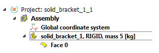
Identify Rigid Parts in the Project Tree
Rigid parts are clearly indicated by the word RIGID next to their name along with the mass information in the SimSolid Project Tree, as shown in Figure 1. This provides an easy visual cue for identifying these simplified components in your model.