Mid Mesh
![]()
Introduction
This option is used to extract the mid surface from 2.5D bodies. Depending on the selected element type the extracted bodies will be created with tri/quad elements. It is supported for both CAD and FEM bodies. "Allow quad mesh transition" option generates quad mesh with transition. For more details please refer Allow Quad Mesh Transition.
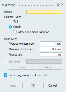
Mesh Size
- Average element size
The Average Element Size is the average element edge length for Tri/Quad elements. The element edge length will vary between (Average Element Size)*Sqrt(2) and (Average Element Size)/Sqrt(2).
- Minimum element size
The Min Element Size is used to remove all the elements that have element edges less than this value.
- Aspect ratio
The quality of mesh can be controlled by setting the Aspect Ratio. The value can vary from 1 (equilateral element) to infinity (straight line). The default Aspect Ratio is set to 10.
End faces
If the tool fails to identify the end faces for the given body, mesh cannot be created. In this situation user can give the end faces to generate mesh.
Show option identifies the end faces automatically and user can review and edit the selection manually. User can clear the end faces using discard option.
Create ring around circle and slot
This option will create one or two layers of elements around circles and slots. For more details, please refer Create ring around circle and slot.
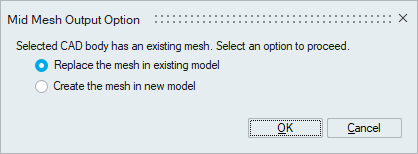
Mid mesh output option for different inputs
- FE Body: The output mesh will be created in a new model.
- CAD Body: The below dialog will prompt the user to select the output location if an equivalent mesh is already present. For more details, please refer Mesh output options for CAD body.
Edge Mesh Control
Users can control the mesh on edges that aren't oriented in the thickness direction by applying edge mesh control. For more details, please refer Edge Mesh Control.
Washer Mesh Control
Users can create rings around a circle by applying washer mesh control. For more details, please refer Washer Mesh Control.
Example 1
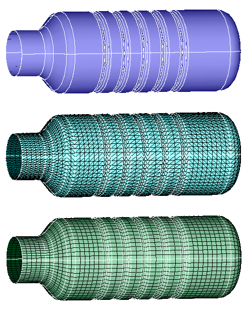
The 2.5D model shown below is meshed with a mesh size of 20 and the output is shown.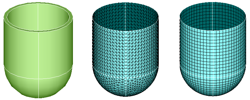
Example 2
The 2.5D model shown below is meshed with a mesh size of 5 and the output is shown.