Grid Mesh
![]()
Grid Mesh
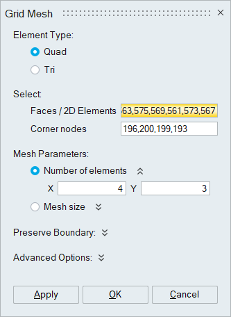
Grid Mesh is used to create map mesh on three/four sided faces. Grid mesh can also be performed on a set of picked 2D elements. User can select one or more faces to create grid mesh.
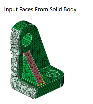
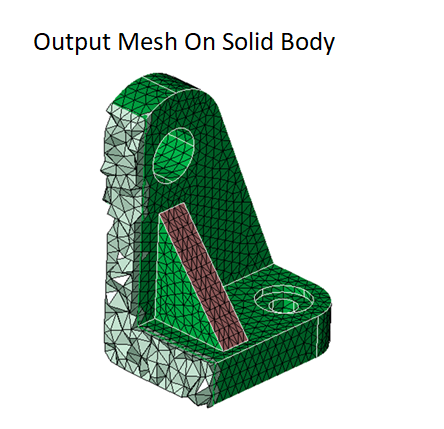
Grid mesh can also be created on a solid mesh body.
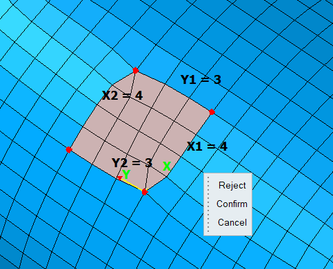
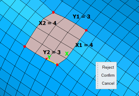
Interactive Mesh EditingUser can edit the mesh interactively with mouse clicks using Number of Elements option.
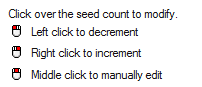
Micro dialog will appear once user selects the input. ‘Reject’ will discard the edited mesh and revert to the input mesh, ‘Confirm’ will apply the edited mesh and ‘Cancel’ is used to clear the selection.

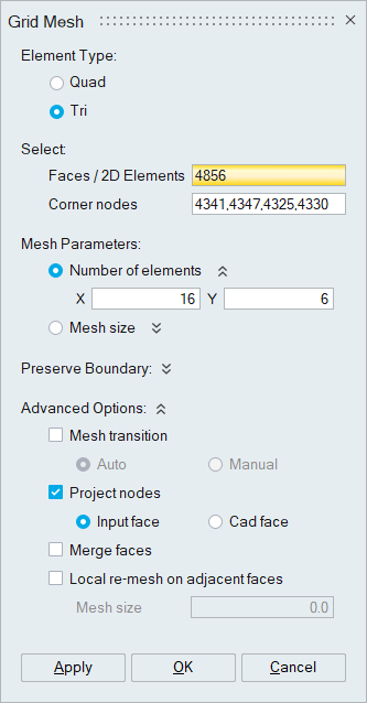
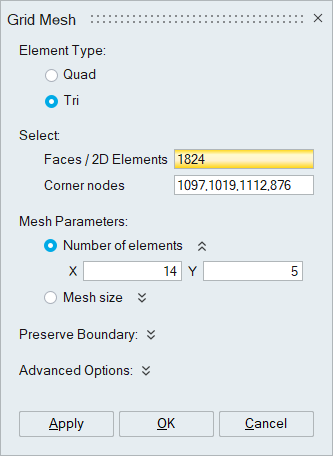
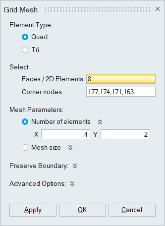
Element Type
Specifies the type of element (Tri/Quad).
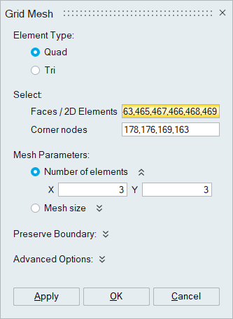
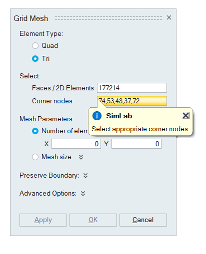
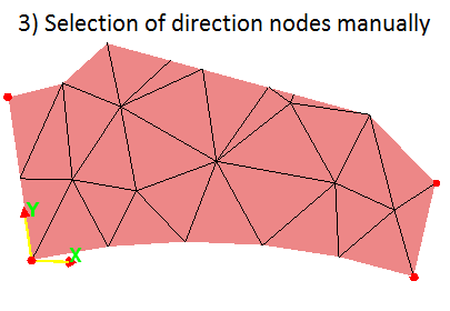
Corner NodesThe corner nodes which determine x and y direction will be displayed automatically while selecting one or more faces/ 2D elements . If the system fails to display the corner nodes, the nodes have to must be selected manually. Nodes can be selected in any order.
User can also select the enclosed 2D elements by picking four corner nodes in a sequence. The boundary will be displayed interactively and upon picking the fourth corner node, the enclosed 2D elements are collected and added to the selection for grid meshing.
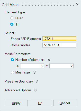
Mesh Parameters- Number of Elements/Mesh Size: Either Number of Elements or Mesh Size can be specified along X and Y directions. By default, the number of elements or mesh size is taken from the existing mesh along the directions.
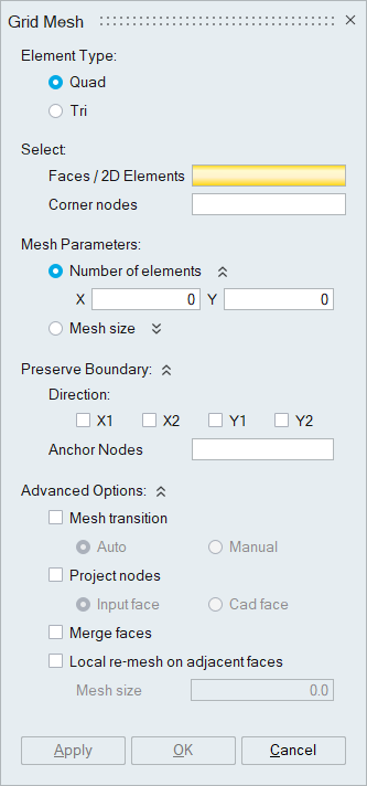
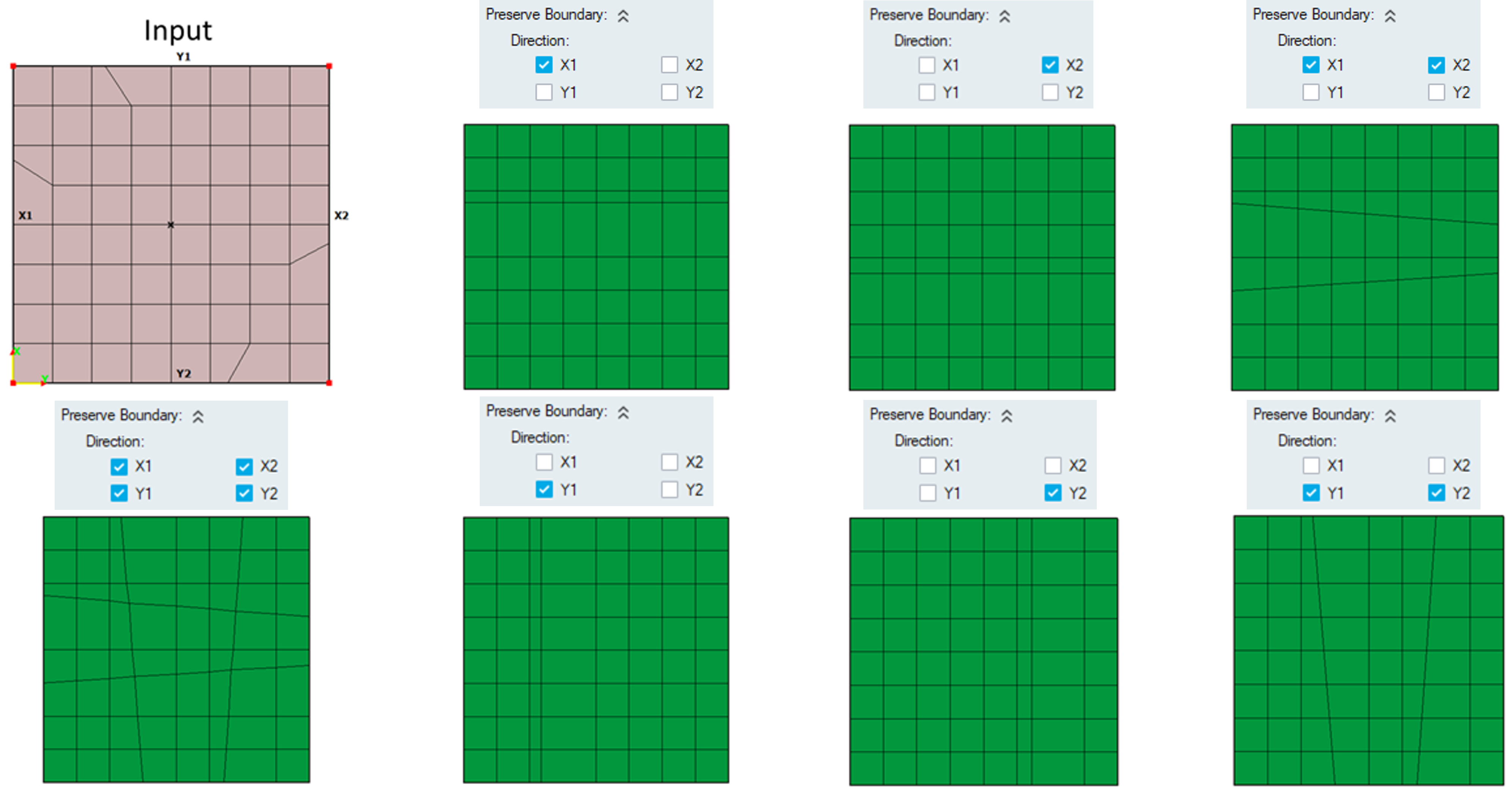
Preserve Boundary
- Direction: User can select the direction that needs to be preserved and rest of the directions will be meshed uniformly.
- Anchor Nodes: Anchor nodes can be selected to preserve the position of the nodes and anchor the mesh flow.
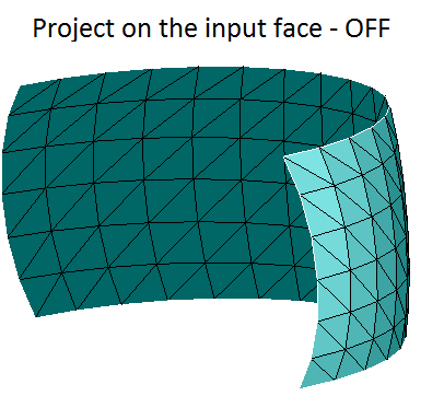
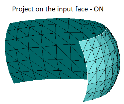
Project Nodes
This will project the mesh on the faces to preserve the geometry. User can either select Input face or Cad face option to project the nodes.
If the Input face option is selected, the nodes will be projected to the input fem face.
If the Cad face option is selected, the nodes will be projected to the corresponding Cad face. If the Cad face is not found, the nodes will be projected on the input face.
Mesh Transition- Auto: User can expect an automatic transition of mesh on four sided faces if the length along a particular direction differs by 25%.
- Manual: This option uses interactive editing to create mesh with user specified element count and obtain the transition manually. "CTRL + Mouse Click" edits the seed count on individual directions without affecting the opposite end. This feature is currently supported for single face input only.
Selected faces will be merged, and grid mesh will be created on the new face. This option is supported only for face input.
Local re-mesh on adjacent facesAdjacent faces will be re-meshed using given mesh size if this option is turned ON. This option is supported only for face input.
Example 1
Modifying the existing mesh into ISO mesh for the given input parameter.

Example 2
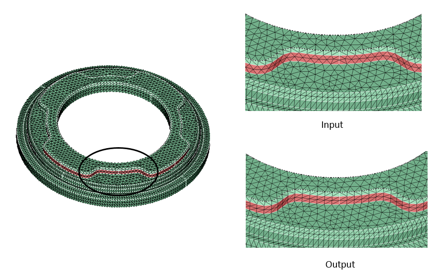
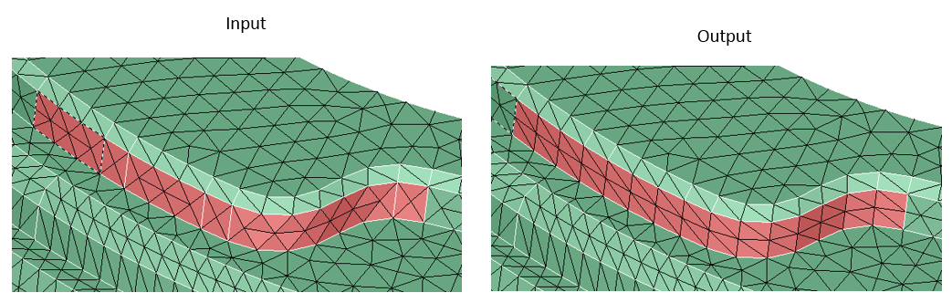
This example will explain the advantage of the Project nodes in capturing the curvature of the input face.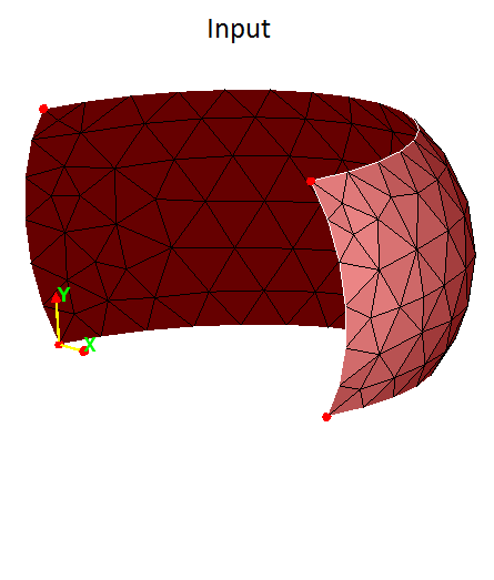
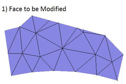
Example 3
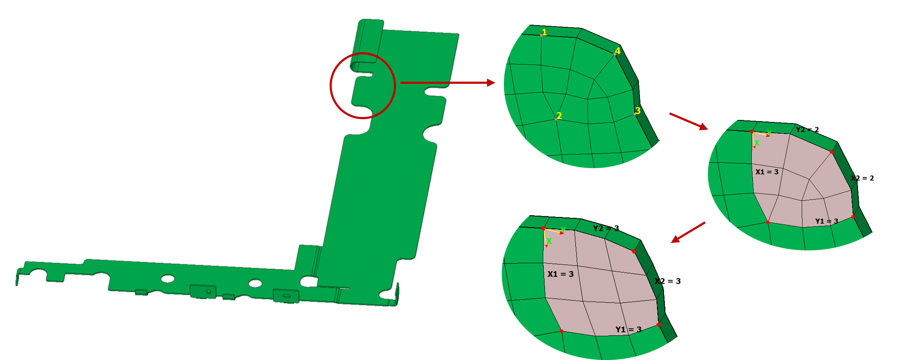
In this case, four direction nodes are not identified automatically. User has to de-select the unnecessary direction nodes manually.
Example 4
Example for preserve boundary option.
Example 5
Multiple face input with merge faces OFF
Multiple face input with merge faces ON
Example 6
Example for Auto mesh transition. Automatic transition of mesh is achieved since the length along the X direction differs by 25%. Seed counts along transition are calculated based on the difference in lengths.
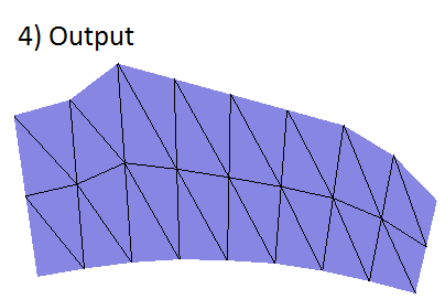
Example 7
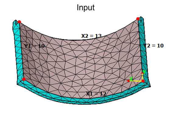
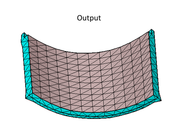
Example for Manual mesh transition. Transition is achieved based on interactive mesh editing using "CTRL + Mouse Clicks" which edits the respective count without modifying the opposite edge.
Example 8
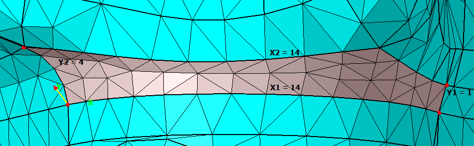
Example for mesh transition based on element edge length. If the cross section of the face varies along the transition direction, the internal seeds are calculated to maintain the average element size of the boundary.
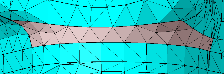
Input
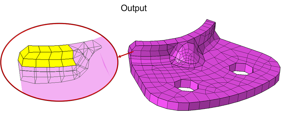
Output
Grid mesh on Tet solid body
User can directly create iso mesh on the faces from solid mesh body. The number of Tet layers that must be modified is controlled using the option Number of Tet-Element layers considered during local mesh modification available under File | preference | mesh. By default, 3 Tet layers will be modified.
Grid mesh on Hex/Wedge body
User can perform Grid Mesh on solid bodies with hex/wedge elements. All the underlying element layers up to the bottom face will be modified based on the new mesh.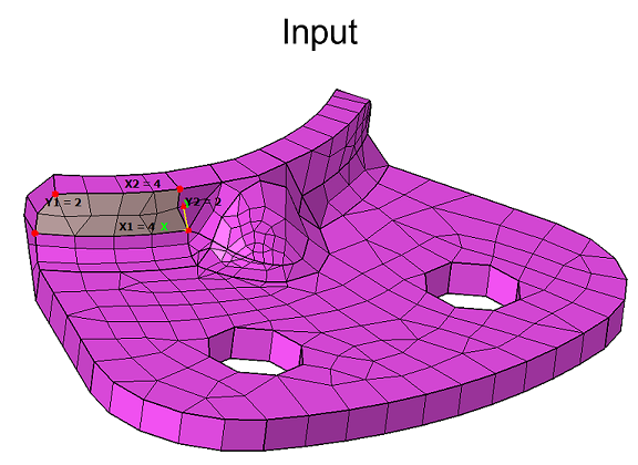
Grid mesh on 2D Elements
User can perform Grid Mesh on set of 2D Elements from shell or solid body.
Input
Output
Grid mesh using four corner nodes
User can pick four corner nodes in a sequence to grid mesh the enclosed 2D elements.