Break Faces
![]()
Dialog Box
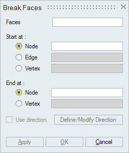
This tool is used to split (break) a face into two or more faces. It also allows to break a face to a specified length marked by a combination of Edge, Node and Vertex. This option is supported for CAD Parasolid models imported with 'Save geometry in database' option, Mesh models with Tri and Quad elements and ECAD models.
Edge-Node/Edge-Vertex
When an edge and a node, (or an edge and a vertex) are selected, the input face will be split starting from the edge till the node (or vertex). Here, the selected node (or vertex) should not be in line with the edge.- Node-Node / Node-Vertex / Vertex-Node / Vertex-Vertex
When two nodes, or two vertices, or a node and a vertex are selected, an edge is created between these two entities. If the selected entities lie on edges, then the face will be split, else a floating edge will be created.
Multiple faces can be given as input and all the selected faces will be listed in the FaceList. Only faces that are selected will be split, even if the face lies between selected entities.