
/H3D/SHELL
Engine Keyword Generate H3D contour output results for /SHELL and /SH3N shell elements.
Format
/H3D/SHELL/Keyword3/Keyword4/Keyword5
#optional next line(s) that lists the parts to save results for.
part_ID1 ... part_IDN
Definition
| Field | Contents | SI Unit Example |
|---|---|---|
| Keyword3 | Output types. | |
| Keyword4 | Output types. | |
| Keyword5 | Output types. | |
| part_IDN | Optional list of part IDs for which results will be output. |
| Keyword3 | Keyword4 | Keyword5 | Description |
|---|---|---|---|
| ALPHA |
|
Shear angle alpha of material /MAT/LAW58 in degrees. | |
| AMS | Elements using AMS timestep due to /DT/CST_AMS. | ||
| BULK | Artificial Viscosity | ||
| DAM1, DAM2, DAM3 | Principal damage values in local orthotropic skew direction 1, 2 or 3 for materials LAW15 and LAW25. | ||
| DAMA |
|
Maximum of damage over time of all /FAIL criteria acting on one material. Refer to the specific /FAIL law used for how damage is calculated. | |
| TMAX | Maximum of damage over time, integration points and failure models. | ||
| DAMG |
|
Mean damage over thickness integration points (only for coupled damage models). 7 | |
|
|
Damage modes for the given material
mat_ID as global damage or for each damage model (adding
MODE= I or ALL). (for MODE output, refer to Comment 13) Available for materials LAW2, LAW25, LAW27, LAW36, LAW72, LAW76, LAW104 + /FAIL/GURSON, LAW122. |
|
| DAMINI |
|
Maximum damage initiation variable among all failure criteria using initiation variable before computing stress softening (/FAIL/INIEVO). | |
| DENS | Density | ||
| DOMAIN | SPMD domain number of an element. | ||
| DT | Element timestep | ||
| EINT | Element internal energy | ||
| EINTV | Element internal energy per unit volume | ||
| ENER | Specific energy density (internal energy divided by the element mass) | ||
| TMAX | Maximum specific energy density over time | ||
| EPSD | Equivalent strain rate | ||
| EPSP |
|
Plastic strain | |
| ERROR | THICK | Estimated error on shell thickness | |
| FAIL |
|
Number of failed layers for /PROP/TYPE10, /PROP/TYPE11, /PROP/TYPE17, /PROP/TYPE51, /PCOMPP, /MAT/LAW15 and /MAT/LAW25. For the other property sets and material laws the values are: no failure =0 and element failed =1. | |
| FAILURE | ID= fail_ID or ALL (mandatory) MODE = I or ALL |
|
Damage of a specific failure
criterion references by its optional identifier fail_ID defined in the Starter file. (for MODE output, refer to Comment 13) |
| FLDF |
|
FLD damage factor indicator. 5 | |
| FLDZ |
|
FLD failure zone factor for the FLD
failure model. 6
|
|
| GROUP | Internal group identifier | ||
| HC_DSSE_F |
|
HC_DSSE damage factor indicator. 11 | |
| HC_DSSE_Z |
|
HC_DSSE failure
zone factor for the HC_DSSE failure model.
12
|
|
| HOURGLASS | Hourglass energy per mass unit | ||
| MASS | Element mass | ||
| MDS | MDS user variables Automatic selection of user variable to output according to MDS law that is used. (1 value per user variable and per ply in case of stack and ply) |
||
|
|
MDS user variables | |
| NL_EPSD |
|
Non-local plastic strain rate (only if /NONLOCAL/MAT is activated) 9 | |
| NL_EPSP |
|
Non-local plastic strain (only if /NONLOCAL/MAT is activated) 9 | |
| NXTF |
|
Instability factor of /FAIL/NXT failure model | |
| OFF | Element status. Where the result
output is:
|
||
| PEXT | External pressure applied on shell element coming from /LOAD/PCYL, /PLOAD, /LOAD/PFLUID, /LOAD/PBLAST or /LOAD/PRESSURE. | ||
| PHI |
|
Angle between the element system and direction 1 orthotropy | |
| SIGEQ | Equivalent stress based on a material’s yield criteria. Some examples of yield criteria are von Mises, Hill or Barlat. | ||
| TMAX | Maximum equivalent stress based on a material’s yield criteria over time . | ||
| SIGX, SIGY, SIGZ, SIGXY, SIGYZ, SIGZX | Stress in specified direction | ||
| TDEL | Time at which element is deleted, due to failure defined using /FAIL criterion. Failure criteria built in materials is ignored. | ||
| TEMP | Temperature | ||
| THICK | Thickness | ||
| THIN | % thinning for shell. | ||
| TSAIWU |
|
Tsai Wu criterion for material /MAT/LAW15 (CHANG) and /MAT/LAW25 (COMPSH) | |
| USER |
|
User material (/MAT/USERij) law output for user-defined variable i. Also, requests USR output for some Radioss material laws such as LAW58. USR1 output is requested using UVAR=1. | |
| VONM | von Mises stress at neutral fiber | ||
| TMAX | Maximum von Mises stress at neutral fiber over time. | ||
| WPLA |
|
Plastic work for /MAT/LAW15 (CHANG) and /MAT/LAW25 (COMPSH) |
| Keyword3 | Keyword4 | Keyword5 | Description |
|---|---|---|---|
| TENS | BSTRESS |
|
Backstress tensor for material
/MAT/LAW36 (n=1) and
/MAT/LAW78 (n=1, 2 or 3)
and /MAT/LAW87 (n=1, 2, 3 or
4). ID=-1 returns the sum of all backstress tensors available for the element. |
| EPSDOT |
|
Strain rate tensor | |
| STRAIN |
|
Strain tensor | |
| TMAX | Strain tensor corresponding to the
maximum principal strain (P1) over time and integration
points. Strain tensor corresponding to the minimum principal strain (P3) over time and integration points. |
||
| STRAIN_ENG | -- | Infinitesimal total strain. Only one tensor per element. | |
| STRESS |
|
Stress tensor | |
| TMAX | Stress tensor corresponding to the
maximum principal stress (P1) over time and integration
points. Stress tensor corresponding to the minimum principal stress (P3) over time and integration points. |
Examples
/H3D/SHELL/TENS/STRESS/PLY=1/NPT=ALL
/H3D/SHELL/TENS/STRESS/NPT=ALL/PLY=1/H3D/SHELL/TENS/STRESS/NPT=ALL/H3D/SHELL/ENER
356 293/H3D/SHELL/USER/NPT=ALL/UVAR=12Comments
- The syntax /H3D/ELEM/Keyword3/Keyword4/Keyword5 is also valid.
- When PART IDs are listed after the /H3D/SHELL line the specified results will output only for those parts.
- The output location in
Keyword4 and Keyword5 can be defined
via:
- NPT
- Integration points for properties /PROP/TYPE1 (SHELL), /PROP/TYPE9 (SH_ORTH), /PROP/TYPE19 (PLY) or /PLY.
- LAYER
- Composite shell layer when using /PROP/TYPE11 (SH_SANDW), /PROP/TYPE10 (SH_COMP), /PROP/TYPE16 (SH_FABR).
- PLY
- Composite shell ply when using, /PROP/TYPE19 (PLY) or /PLY.
- MEMB
- Generalized membrane stresses per element. Cannot be used with NPT, LAYER or PLY options.
- BEND
- Generalized bending stresses per element. Cannot be used with NPT, LAYER or PLY options.
- Output can be requested for a specific location number (I), ALL, and in some case UPPER or LOWER. The output locations are separated by a / and can be in any order.
- The values of FLD damage factor
is equal to the ratio of the actual major principal strain value over the
forming limit curve value:
Where, is the major principal strain at failure limit from FLD diagram (fct_ID in /FAIL/FLD).
The FLD compares the and using the same .Figure 1. 
FLDF may be greater than 1, if the option /FAIL/FLD, Ifail_sh=4 is used. In this case, the damage factor is only calculated for post-processing and no elements are deleted.
- The values of FLD zone index are
defined as:
- FLDZ=6
- Failure
- FLDZ=5
- Marginal
- FLDZ=4
- Safe
- FLDZ=3
- Compression
- FLDZ=2
- High wrinkle
- FLDZ=1
- Loose metal
Figure 2. 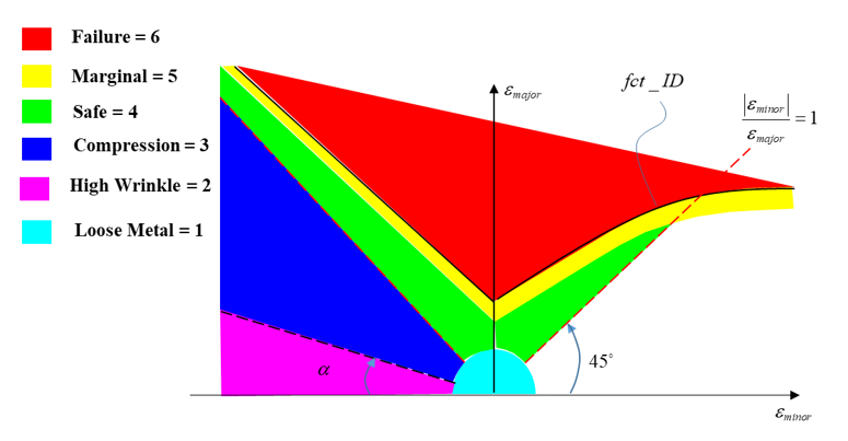
Where,- fct_ID
- Defined in /FAIL/FLD
- Major strain as a limit from FLD diagram from fct_ID in /FAIL/FLD
- and
- The minimum and maximum principal strains
- Rani
- Average anisotropy factor defined in FLD input in /FAIL/FLD
- Defined in FLD input in /FAIL/FLD
- Defined in FLD input in /FAIL/FLD
- I_marg
- Defined in FLD input in /FAIL/FLD
- Option DAMG is
only used with coupled damage models (such as /MAT/LAW72 or
/FAIL/GURSON) to output damage over integration points.
The damage variable is normalized by its critical value to get values between 0
and 1. For instance:
- For /MAT/LAW72
- For /FAIL/GURSON
- For /MAT/LAW72
- When using global integration (N=0 in the shell property), Radioss always outputs the stress and strain only in the midplane (MEMB).
- If /NONLOCAL/MAT option is activated, it is possible to output the regularized non-local plastic strain and its rate.
- The damage initiation variable /H3D/SHELL/DAMINI is used with some failure criteria such as /FAIL/INIEVO, which first computes a damage initiation criterion before computing the stress softening damage variable, which can be plotted with /H3D/SHELL/DAMA.
- For
HC_DSSE_F, the value of HC_DSSE damage
factor is equal to the ratio of the actual plastic strain value over the plastic
strain at failure curve value:Where, is the plastic strain at failure defined by Hosford-Coulomb curve (see /FAIL/HC_DSSE).
Figure 3. 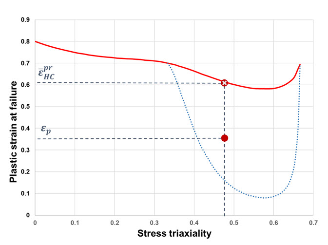
- For
HC_DSSE_Z, the value of HC_DSSE zone index
are defined as:
- HC_DSSE_Z = 1 (Safe)
- Below HC and DSSE curves
- HC_DSSE_Z = 2 (Necking)
- Above DSSE curves and below HC curve
- HC_DSSE_Z = 3 (Failure)
- Above DSSE and HC curves
- For failure criteria using different modes (mainly for composites), such as /FAIL/HASHIN, /FAIL/CHANG, and so on, these different modes can be output using the /H3D/SHELL/FAILURE option with the keyword MODE. You can choose to plot a specific mode using its number I (refer to the failure criterion documentation for mode number details), or all modes with ALL. The option MODE can be combined with PLY, LAYER and NPT output keywords.