Dummy Positioning
Position a dummy model using the Dummy Browser.
Dummy Browser
Overview of the Dummy Browser.

This browser is compatible with all LS-DYNA, Radioss and PAM-CRASH Humanetics dummies (encrypted or not encrypted) and also with LSTC dummies.
You can undo and redo actions made in the browser using the Undo and Redo commands on the Restore toolbar.
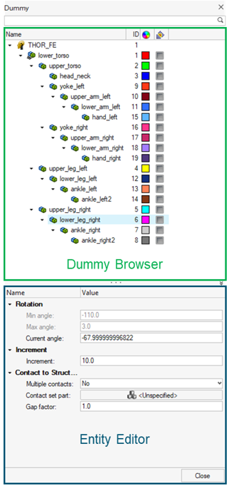
| Column | Description |
|---|---|
| Entity | List of the dummies and dummy bodies. |
| ID | Displays the dummies and bodies IDs. |
| Color | Displays the body entity colors. Body color is different from the component color defined in the Model Browser. The body color is activated when a body is in Review mode or when display mode is set on “By Body”. |
Entity Editor
The Entity Editor is used to assign, modify and quickly view the attributes defined inside Dummy Browser entities.
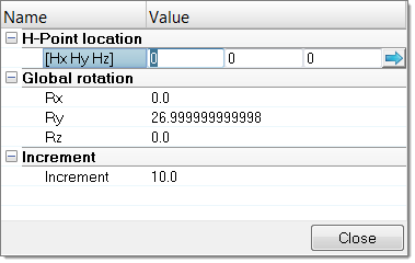
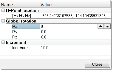
The Entity Editor is also used to modify the position of bodies. You can directly define the angle of rotation to apply in each axis of rotations in which the selected body is able to move.
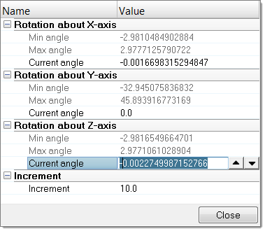
Context Menu
Supported Entities
The Dummy (![]() ) is the root of the
hierarchy in the Dummy Browser. A dummy is defined by bodies
(
) is the root of the
hierarchy in the Dummy Browser. A dummy is defined by bodies
(![]() ) representing the
different kinematic assemblies of the dummy.
) representing the
different kinematic assemblies of the dummy.
Position Dummies
Position the Body Manually
- In the Dummy Browser, select a body.
-
In the graphics area, click-and-drag the manipulator to interactively modify
the position of the selected body.
Figure 6. 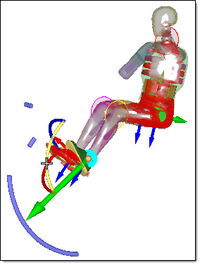
Position the Body Automatically
-
In the Dummy Browser, right-click on a body and select
Move Limbs from the context menu.
The Entity Editor opens.
Figure 7. 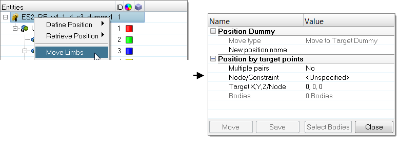
- In the Multiple pairs field, select No (apply option to a single node) or Yes (apply option to a set of nodes and targets).
- If Multiple pairs is set to Yes, click Select pairs to open the Select multi nodes dialog and select nodes and target point pairs.
- Define a Node of a body.
- Define the Target location.
-
Click Select Bodies to open the Dummy Bodies
DOF dialog and select the bodies and degrees of freedom of the
active bodies that will be able to move during automatic positioning.
Select bodies by activating their corresponding checkbox, or picking them in the graphics area (right-click or left-click to activate/deactivate a body). Lock/unlock degrees of freedom by clicking the lock icon, or by picking the DOF arrows in the graphics area (right-click or left-click to activate/deactivate a DOF).
Figure 8. 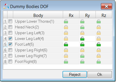
- Click Move to start the automatic positioning process.
-
Click Save to save the achieved position.
A name will be appended to the New position name field.
Contact Detection with Surrounding Components
Auto-contact detection allows you to automatically detect contact between dummy limbs and surrounding structural components during the positioning process. Limb motion is automatically stopped on contact detection.
- In the Dummy Browser, select the dummy body.
- In the Entity Editor, select either single contact or multiple contacts that need to be defined by setting Multiple contacts to Yes or No.
- For each contact, create and assign a set of components in the Contact set part field.
- In the Gap factor field, type in an appropriate scale factor.
-
Click Close.
The Contact checkbox is activated for the selected dummy body indicating the contact check is active.
Figure 9. 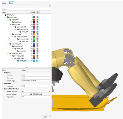
Position Dummies with Test-Lab Data
Automatically position a FE Dummy model based on test-lab coordinates measurements data.
- In the Dummy Browser, right-click the dummy root name and select Dummy Testdata Positioning from the context menu.
- Define H-Point location coordinates of the dummy H-Point.
- Define the Rx global dummy rotation value around the global X-axis.
- Define the Ry global dummy rotation value around the global Y-axis.
- Define the Rz global dummy rotation value around the global Z-axis.
-
Select the Creation method.
- Scan from outputblock: Scans a selected nodal history output keyword (*DATABASE_HISTORY_NODE for LS-DYNA or /TH/NODE for Radioss) and looks for names containing the Name pattern if it is activated. For each node found, a target point is created.
- From nodes selection (the manual method): Create a target point on all of the selected nodes on the dummy. Each target point is created with a name starting with the Point prefix string.
- Import the dummy target file. Select a .csv file containing the test measurement coordinates for the target points defined on the dummy.
-
Define Skip lines in csv file on import.
The number of lines at the beginning of the .csv file that need to be ignored from the reading process.
-
Select Target points on the dummy.
The tool controls these during the automatic positioning.
- Select the Targets priority to apply for the control of the target points during the positioning.
- Select the Export dummy target file where the .csv file, containing the final positioning results for the selected target points, will be exported.
- Click Create to create the Target points based on the Creation method.
- Click Import to enable the reading of the .csv file containing the measurements data.
- Click Select Bodies to select the dummy bodies or DOFs that will be considered during the automatic positioning of the dummy.
- Click Move to start the automatic positioning process.
- Click Export to export the .csv file with the final positioning information.
- Click Close.
Setup Pre-Simulation
Export an input deck to simulate the deformation of the dummy.
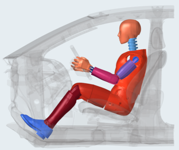
The method used for the pre-simulation is known as the “cable” method, which uses 1D elements connected to dummy bodies, in order to pull them from their initial position to their final position.
All “cables” are automatically created on each dummy body and all boundary conditions needed for the pre-simulation.
The simulation result files can be imported to update the initial FE model and thus remove the intersections and penetrations between the dummy components.
- Only Dummy: Export the solver files to perform the simulation of the dummy deformation only.
- Dummy with Seat: Export the solver files to perform the simulation of the dummy and the seat deformation in one step.
Only Dummy
- In the Dummy Browser, right-click on the dummy and select from the context menu.
-
In the PreSimulation Tool dialog, define settings
accordingly.
- Define PreSimulation Tool Options accordingly.
- Click Export.
Dummy with Seat
- In the Dummy Browser, right-click on the dummy and select from the context menu.
-
In the PreSimulation Tool dialog, define settings
accordingly.
- Define PreSimulation Tool Options accordingly.
-
Click Export.
To update the model with simulation results, import the simulation result file, which allows the dummy node's coordinates to be updated and element initial stress state to be defined.
- For LS-DYNA, click Import dynain File to find the .dynain file.
- For Radioss, click Import h3d File to find the .h3d file.
PreSimulation Tool Options
Overview of supported options in the PreSimulation Tool.
LS-DYNA
- Simulation Parameter
-
- Simulation Time
- Define the total simulation time in *CONTROL_TERMINATION for the pre-simulation.
- Time Step
- Define the control time step value in *CONTROL_TIMESTEP for the pre-simulation.
- Force in cables (valid for the Force Based option only)
- Define the pre-tension force to be applied on the cable elements in *MAT_CABLE_DISCRETE_BEAM.
- Force ramp up time (valid for the Force Based option only)
- Define the ramp-up time for the pre-tension force in *MAT_CABLE_DISCRETE_BEAM.
- Damping on cables (valid for the Force Based option only)
- Define the damping value on the discrete elements in *MAT_DAMPER_VISCOUD.
- Global damping value
- Define the system damping constant in *DAMPING_GLOBAL.
- Initial Stress Results
-
- Import *INITIAL_STRESS_SOLID
- Import the initial stresses for solid elements from the .dynain file.
- Import *INITIAL_STRESS_SHELL
- Import the initial stresses for shell elements from the .dynain file.
- Import *INITIAL_STRESS_BEAM
- Import the initial stresses for beam elements from the .dynain file.
Radioss
- Simulation Parameters
-
- Generate XREF for initial stresses
- Create /XREF cards for the dummy components which are compatible with this RADIOSS feature in terms of material type and element formulation. The XREF cards are generated within the original session during the export of the pre-simulation deck, and not during import of .h3d file.
- Simulation time
- Define the total simulation time in /RUN card for the pre-simulation.
- Time Step
- Define the control time step value in /DT/NODA/CST card for the pre-simulation.
- Global damping value
- Define the system damping constant in /DAMP card.
- Create rigids for end bodies
- Automatically rigidify the end bodies (feet, hands, head) of the dummy during the pre-simulation.