Use the Fmvss201U Marking tool to streamline the vehicle marking process by
incorporating necessary input data for vehicle parts.
Simultaneously, the Fmvss201U Positioning tool efficiently handles the positioning of
impactors and exports solver decks with minimal input from you. This not only
simplifies the processing of this intricate regulation but also expedites the
initiation of simulations, saving valuable time. This tool supports both left and
right-hand drive vehicles.
Restriction: Only available in the LS-DYNA,
Radioss and PAM-CRASH profiles.
The tool is accessible from the Safety ribbon. A pull-down
menu provides a choice between the Marking and
Positioning workflows.Figure 1.
The FMVSS 201U tool exports the primary file automatically for each chosen impact
point, seamlessly integrating the impactor include file and transformation cards. It
is essential to pre-prepare the main files for each impact load case with the
required include files, excluding the impactor include, as part of the preliminary
setup.
FMVSS 201 U Marking
Click on the guide bar to define
marking options.
Method
Marking methods:
Automatic
The marking is performed as per the FMVSS 201U
regulation.
Test Lab
Import the impact points coordinates data in CSV format
file.
Manual
Impact locations defined by selecting nodes on the
interior parts of the vehicle.
Testing Side
Marking can be done on both sides of the vehicle, either the left or
right side.
Vehicle Front Axis
Orientation of the vehicle -X or +X.
H-Point Offset
Method to define the seat reference point offset:
None
No offset point.
XZ Offset
As per the regulation, with translation in X and Z
directions.
Travel Vector
User-defined translation vector.
Weather Stripping offset
If weather stripping is not available in the vehicle model, you can
add the offset value for it, which can affect the APR point
calculation.
Windshield offset
If the vehicle model does not include any windshield frame parts,
you can provide a windshield offset value, which will be utilized to
calculate the APR.
Import Selections
You can conveniently retrieve previously selected essential data
from a saved CSV file, thus saving valuable time that would
otherwise be spent repeating the selection process.
Save Directory
Directory for saving the selection in CSV format.
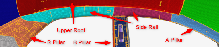
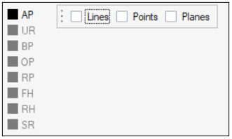
Automatic Marking
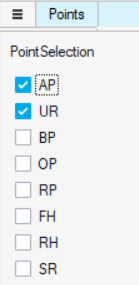
Select the standard impact point areas where impact points marking will be done
with automatic marking.
Figure 2.
AP – A Pillar
UR – Upper Roof Area
BP – B Pillar
OP – Other Pillar
RP – Rear Pillar
FH – Front Header
RH - Rear Header
SR – Side Rail Area
By default, AP and UR are selected as further point selection is dependent on
the APR point and upper roof area marking.
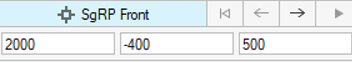
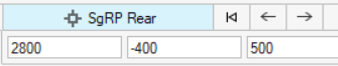
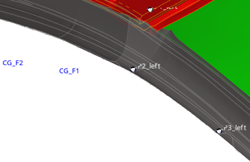
Enter seating reference points.
Enter SgRP Front and SgRP Rear points coordinates.
Select the point location in the modeling window.Figure 3. Figure 4.
The points CG-F1 and CG-F2 are calculated with reference to SgRP Front and
CG-R is calculated with reference to SgRP Rear.
On the guide bar, click
and to navigate through the selections for the
different windows and frames.
Select several required areas/parts of the vehicle mentioned in FMVSS201
regulation to achieve correct result.
Exterior Parts: Selection of outside BIW parts above Pillars and the
Roof parts.
Interior Parts: Selection of all Pillar trims, Headliner parts.
Windshield: Selection of Windshield and the trim surrounding it.
Select the trim parts to which impact points will be marked.
Selection is disabled until you select the required parts.
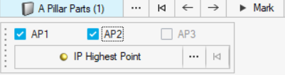
Select A Pillar parts for marking of AP1, AP2 and AP3 legal impact
points.
Figure 5.
AP1 or APR is computed based on vehicle data in accordance with regulations,
utilizing selected parts. If Windshield offset and/or Weather stripping
offset are entered in the hamburger menu, the APR is then determined by the
provided values. AP2 and AP3 points are contingent upon APR, with no
additional definitions needed for AP2.
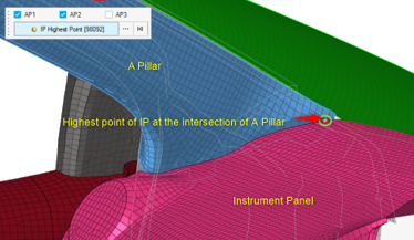
For AP3 points, you must input the highest point of intersection between the
instrument panel and the A Pillar trim. This can be achieved by selecting a
point or using advanced selection methods.Figure 6.
Once all definitions are completed in this microdialog,
click Mark to start the automatic calculation of design
points.
The design points display in the Model Browser.Figure 7.
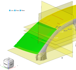
Construction entities
Upon marking in compliance with
regulations, geometric generation of points, lines, and planes takes place.
You can utilize the legends available under the context guide bar to display and verify the construction of design
points.Figure 8. Figure 9.
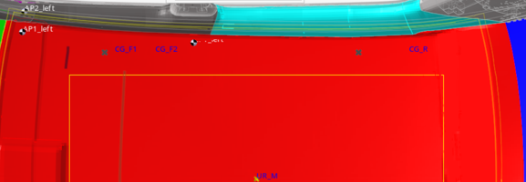
Upper Roof Zone is to be marked by selecting only interior roof parts. As per
the regulation with the use of APR, UR zone will be marked on interior roof
parts with the Center M marking.
Figure 10.
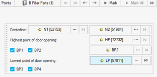
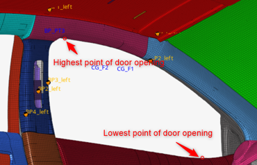
Next is the selection of B Pillar area for marking. In the microdialog associated with it select two centerline nodes to
define centerline. Additionally, highest point of front door opening is needed.
With this input you can mark BPR (B Pillar Reference point) BP2 can be picked up
anywhere on seat belt anchorage.
Figure 11.
For BP3 point Lowest point of door opening reference needs to be selected. For
BP4 point no extra input is needed.
Figure 12.
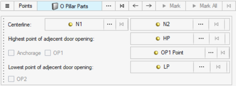
If the vehicle model contains other Pillars (C or D Pillar) besides B Pillar
and rear Pillar you can select the Pillar and define the impact points with the
similar workflow inputs as B Pillar as shown in following microdialog.
Figure 13.
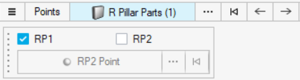
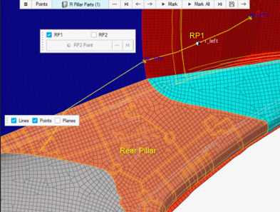
The RP1 point for Rear Pillar needs only Rear Pillar parts to be selected. If a
seat belt anchorage is located on the Rear Pillar, then RP2 can be selected
anywhere on seat belt anchorage.
Figure 14. Figure 15.
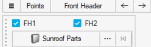
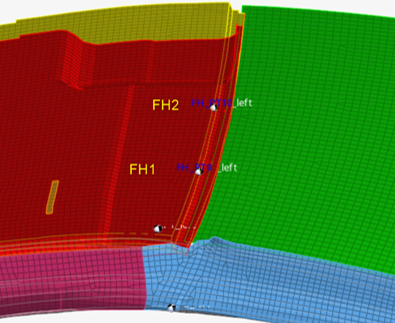
For the identification of FH1 and FH2 on the front header, no special
definition is necessary. If the vehicle is equipped with a sunroof, select
Sunroof Parts in the selection.
FH2 will be appropriately marked on the sunroof opening.Figure 16. Figure 17.
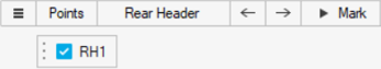
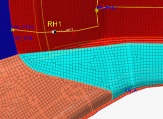
For calculating RH1 point on rear header no further definition is required.
Activate the checkbox for RH1 and click Mark.
Figure 18. Figure 19.
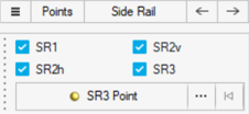
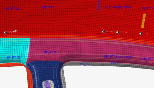
After switching to side rail marking, for side rail targets min. required
definitions are APR and UR lines. No further definitions are required for
SR1.
There are two SR2 targets. One is behind APR (v) and another is front of BPR
(h) and can be calculated when APR, BPR and UR lines are available. SR3 points
prerequisites BPR, which will be marked behind B Pillar automatically. If there
is seat belt anchorage or grab handle located on the side rail you can select
SR3 point anywhere on those parts.Figure 20. Figure 21. With this marking procedure is finished for all legal points according to
FMVSS 201 U regulation.
You can click Mark All at the end of the workflow,
instead of clicking Mark for all the targets.
Click the Save icon to save all of these
selections and reference points.
Selections will be saved in the .csv file in the
working directory specified in the hamburger menu. You can retrieve these
selections by importing this file if the model is the same with minor
changes.
Click the arrow next to the Save icon to redirect to the FMVSS 201U Positioning
workflow.
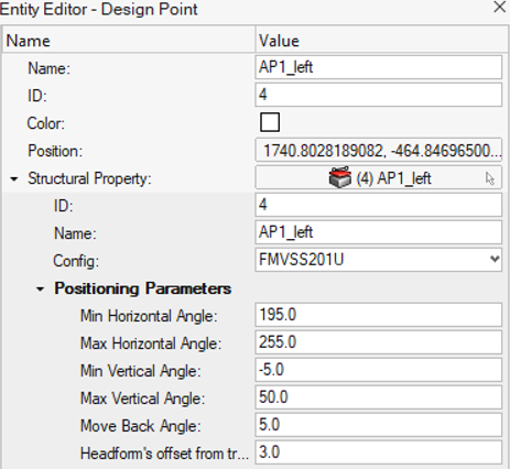
Each designated impact point can be accessed in the Design Points entity
listed in the Model Browser providing comprehensive data on
the point, including its structural properties.Figure 22.
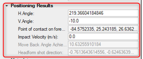
Positional parameters according to the regulation are important for
positioning the headform within the allowable approach angles and move back
angle allowed. Under positioning results, achieved approach angles, point of
contact on forehead, move back angle achieved, headform shot direction data
achieved after the positioning are inputted by the tool.
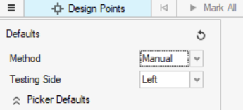
Manual Marking
Manual marking allows you to create a Design Point entity at a selected location on
interior parts. A minimum of Design Point entity metadata can be specified in the
options menu.Figure 23.
Select the impact location from the guide bar.
Click Mark All to automatically generate the Design
Point entities.
Figure 24.
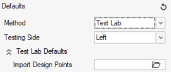
Test Lab Marking
Test Lab marking allows you to directly read a CSV file containing the information
for the impact locations that a test laboratory can provide.
Select the CSV file from the options menu options.
Click Mark to automatically create the Design Point
entities at the defined locations.
Figure 25.
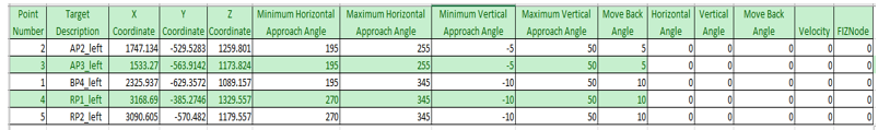
Here is an example of a CSV file:Figure 26.
FMVSS 201 U Positioning
The following are the prerequisites for the positioning workflow:
Vehicle model with target impact points marked on interior areas of
interest.
Free motion Headform (FMH) model with Forehead impact zone marked with
designated part.
Main input file ready with required include files referenced.
After importing the vehicle model and FMH you can start the positioning workflow.
Click on the guide bar to define
positioning options.
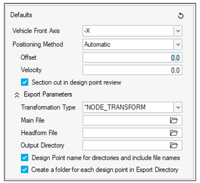
Vehicle Front Axis
Orientation of the vehicle -X or +X.
Positioning Method
Automatic
Default way of positioning the FMH automatically.
Manual
Manipulate the FMH and position it.
Offset
Offset value of FMH from the impact point.
Velocity
Impact velocity.
Section cut in design point review
Review positioned FMH in section cut.
Export Parameters
Transformation Type
Choose between the following solver transformation
definitions for the impactor position.
LS-DYNA
*NODE_TRANSFORM
*INCLUDE_TRANSFORM
Radioss
/GRNOD
//SUBMODEL
PAM-CRASH
TRSFM/
Main File
File path to the main input deck to be used for the
generation of the decks.
Headform File
File path to the headform input deck to be used as the
include file in the main input deck.
Output Directory
Directory where all solver decks for the selected impact
locations to be simulated are created.
Design Point name for directories and include file
names
This option takes the name of the Design Point entity
for the creation of sub-folders and solver deck
names.
Create a folder for each design point in Export
Directory
When activated, this option creates a sub-folder per the
selected target point in the Output Directory location.
When not activated, all main decks and includes are
written in the Output Directory location.
Select the entities required.
On the guide bar, click
and to cycle through the entity types of the
positioning process.
Select interior trim parts where head positioning is to be
executed.
Figure 27.
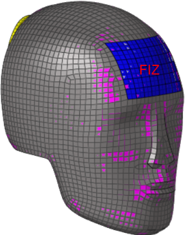
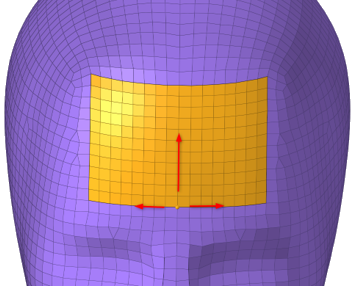
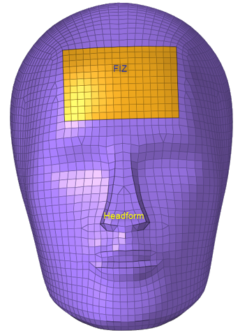
Select the Free motion Headform parts and next Forehead Impact zone
(FIZ) part.
Figure 28.
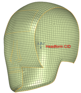
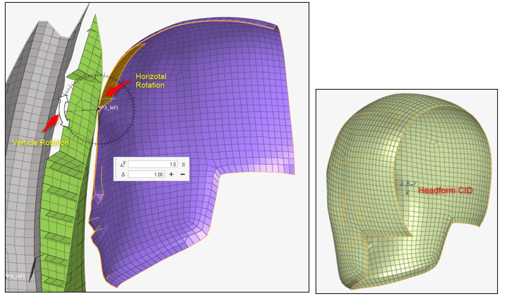
Select the Headform CID coordinate system as
reference system along which vertical and horizontal rotation angles for
FMH will be calculated.
Figure 29.
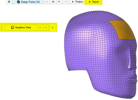
Select the design points (already marked) where the FMH is to be
automatically or manually positioned and click
Position.
Figure 30.
The tool will attempt to automatically position the headform based on the
specified horizontal, vertical, and backward angle in the positioning parameters
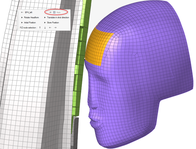
for each point.Figure 31. Automatic Positioning of FMH on Trim
If a suitable position is identified, the Auto checkbox will be marked,
and the configuration will be saved. Automatic Positioning: Initially, the
FIZ node at the center of the Forehead Impact Zone aligns with the target
impact point, and the FMH is positioned to ensure alignment of the FIZ
normal vector with the normal of the target point. The distance between them
is minimized, taking into account any specified offset in the hamburger
menu. The specified range of horizontal and vertical approach angles, as
outlined in the regulation, is honored.Figure 32. Positioning Parameters According to Regulation
The microdialog for positioning will
also include manual positioning tools. If automatic positioning is
unsuccessful, the headform will return to its initial position, with the
Trim node and FIZ node normals aligned to each other.Figure 33. Microdialog for Positioning
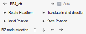
You can navigate through design points using the arrows and
observe whether they are automatically positioned or not.
Rotate Headform
Manual rotation of FMH in horizontal and vertical
direction.
Vertical rotation will utilize the Y-axis of the system attached
to the headform, while horizontal rotation will involve the
Z-axis of the system.Figure 34. Rotation Angles for FMH
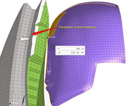
Translate in shot direction
You can translate the FMH in shot direction, that is, in X
direction of FMH system to verify first point of contact to the
trim surface.Figure 35. Translate in Shot Direction
Initial Position
Reset FMH at initial position at target point.
Store Position
Store the auto/manual FMH position to export.Figure 36. Metadata Stored for Positioned Impact Point
When you click Store position, the design
point will be saved along with its position metadata, which can be exported.
If this option is not enabled during manual positioning, the information
will not be included in the export.
FIZ node selection – Select FIZ
node on forehead for positioningFigure 37. FIZ Node Selection
During manual positioning, you attempt to identify the
appropriate position by adjusting the node on the Forehead Impact Zone
(FIZ), while adhering to the allowable angles. To facilitate this,
incremental shifting of nodes is enabled through the use of vertical and
horizontal node selection arrows.
After successfully positioning the FMH, click Export to
export the impact point positions.
This will export solver decks for all stored/auto positioned design
points.
Before performing this operation, you should ensure that the
Export Parameters mentioned in the hamburger menu are correctly
configured.
If you want to export the headform deck, you can use the
Transformation type *INCLUDE_TRANSFORM in the LS-DYNA profile and //SUBMODEL in Radioss. Another
option is to export the headform data using NODE_TRANSFORM in LS-DYNA and /GRNOD in the Radioss profile. For PAM-CRASH, the default transformation type is TRSFM/.
In the later case you need to select the parts of the headform which are
needed for the export.Figure 38. Export of Positioned Impact Points
Tip: Click after each selector to reset your selection.
Pre-Requisites on the Headform Model
From the FMH impactor, you need to extract the outside shell element surface and
define Forehead Impact Zone (FIZ) on that shell property that is used for
positioning.Figure 39. Headform Model
Export Solver Decks
This tool enables you to export ready-to-run solver decks for all of the impact
locations.
In the UI Impact Positioning workflow, provide the information in the Export
Parameters.
Figure 40.
The Main File is the user-defined main input deck containing the include
structure of the final model (Upper Interior model, contacts, controls,
boundary conditions, …)
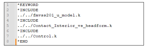
Here is an example of a Main File for LS-DYNA:Figure 41.
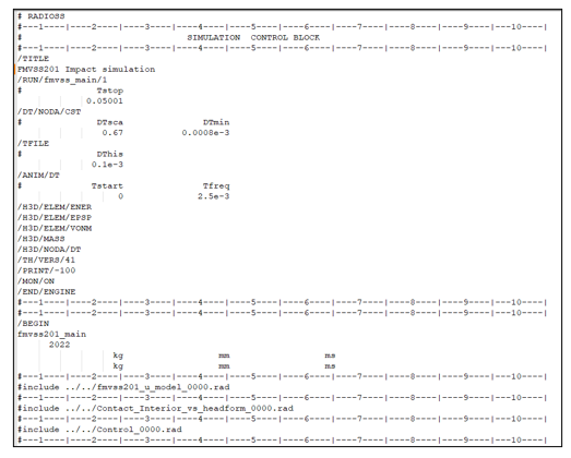
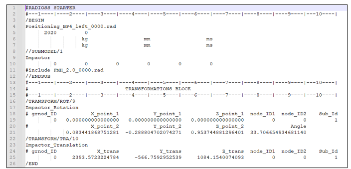
Here is an example for Radioss:Figure 42.
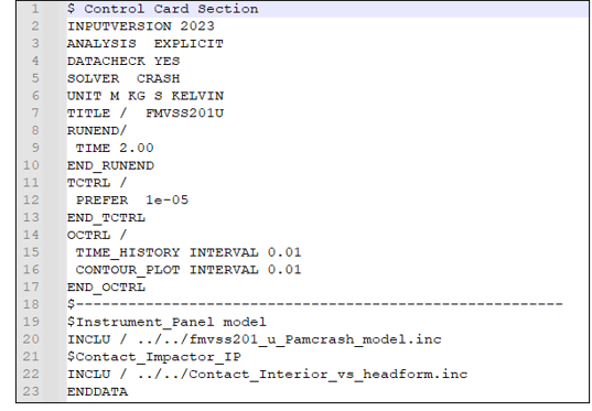
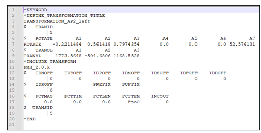
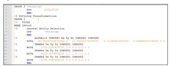
And here is an example for PAM-CRASH:Figure 43.
Headform File should point to the headform model that the tool will define as
an include in the Main File during the export of the decks.
The Output Directory is the location where all of the solver decks for each
impact location are written out.
During the export process, the tool generates an additional include file
containing the transformations to apply on the impactor using the
Transformation Type.
Here is an example of positioning Include file generated by the tool:Figure 44. LS-DYNA Figure 45. Radioss Figure 46. PAM-CRASH
Finally, the positioning file is automatically added as an include file in
the Main File. The resulting model files for each impact location look as
follows:
 and
and  to navigate through the selections for the
different windows and frames.
to navigate through the selections for the
different windows and frames.
 to save all of these
selections and reference points.
Selections will be saved in the .csv file in the working directory specified in the hamburger menu. You can retrieve these selections by importing this file if the model is the same with minor changes.
to save all of these
selections and reference points.
Selections will be saved in the .csv file in the working directory specified in the hamburger menu. You can retrieve these selections by importing this file if the model is the same with minor changes.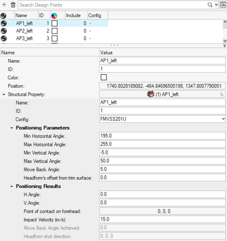

 on the guide bar to define
positioning options.
on the guide bar to define
positioning options.