IP Impact
Use the IP Impact tools to automatically calculate the instrument panel (IP) testing area according to the regulations FMVSS201 and ECE-R21, position the headform impactor, and export ready-to-run solver decks for all the selected impact locations.
IP Marking
-
Click
 on the guide bar to define
marking options.
on the guide bar to define
marking options.
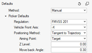
- Method
- Marking method:
- Vehicle Front Axis
- Orientation of the vehicle -X or +X.
- Regulation
- Regulation to be followed for the marking: FMVSS201 or ECE-R21.
- H-Point Offset
- Method to define the seat reference point offset:
- Target Points
- Method to define the target points locations:
- Intermediate Curves
- Creates additional curves and impact locations between the upper and lower impact zone limits.
- LHS Area Limit
- Left limit of the impact zone according to the regulation.
- RHS Area Limit
- Right limit of the impact zone according to the regulation.
- Arm Length
- Arm length used for calculating pendulum positioning parameters.
- Min Length
- Minimum pendulum arm length for the lower limit of the impact zone according to the regulation.
- Max Length
- Maximum pendulum arm length for the lower limit of the impact zone according to the regulation.
- Headform Dia
- Headform diameter according to the regulation.
- Rotation Step
- Angle of rotation between two pendulum positions to create the lines on the IP.
-
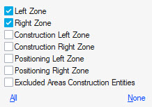
For the Automatic and Manual methods, select the entities required.
Click
 and
and  to
cycle through the entity types for the marking process.
to
cycle through the entity types for the marking process. -
Click Mark to start the marking process.
The button becomes active when at least the Instrument Panel entities are selected.
-
Click at the end of the guide bar
to move to the IP Positioning workflow.
Automatic Marking
Steering wheel and Windshield can be selected for the calculation of the limits of the impact area as defined in the regulation.
At the end of the marking workflow, the following entities are generated:
- Geometrical lines
- Defining the upper and lower limits of the impact area.
-
Figure 3. Geometrical lines 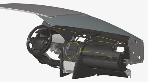
- Sphere surfaces
- Defining the construction of the upper limit for the FMVSS201 regulation.
-
Figure 4. Upper limit line construction spheres 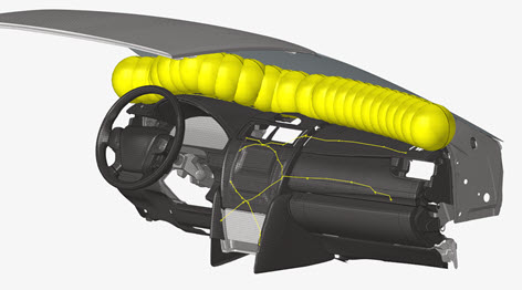
- Planes
- Defining the right and left limits of the impact area as per the regulations.
-
Figure 5. Planes for right and left limits 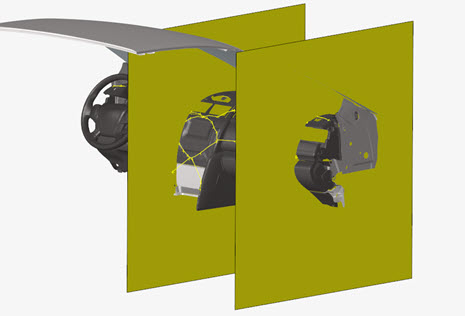
- Impactor geometries
- Defining the position of the impactor used for the impact area lines generation.
-
Figure 6. Impactor position for lines construction 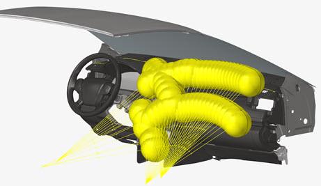
- Design Points entities
- Defining entities at the calculated impact locations.
-
Figure 7. Target points entities at impact locations 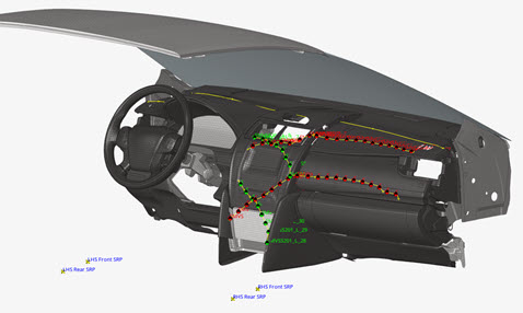
- Impactor geometries
- Defining the pre-calculated impactor position with the given Arm Length.
-
Figure 8. Impactor position for given Arm Length 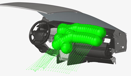
Manual Marking
Manual marking allows you to create a Design Point entity at a selected location on the IP. A minimum of Design Point entity metadata can be specified in the options menu.
Select the impact location from the guide bar. Click Mark to automatically generate the Design Point entities.

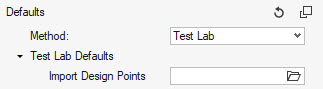
Test Lab Marking
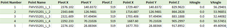
Test Lab marking allows you to directly read a CVS file containing the information for the impact locations that a test laboratory can provide.
Select the CSV file from the options menu options then click Mark to automatically create the Design Point entities at the defined locations.
Here is an example of a CSV file:
IP Positioning
After the creation of Design Points from the Marking process, the Positioning workflow is used to:
- Calculate the position of the impactor for all the selected Design Points.
- Visualize the position of the impactor.
- Export ready-to-run solver decks for all the selected Design Points
-
Click on the guide bar to define
positioning and export deck options.
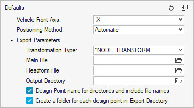
- Vehicle Front Axis
- Orientation of the vehicle -X or +X.
- Positioning Method
- Choose between the following positioning methods:
- Transformation Type
- Choose between the following solver transformation definitions for the impactor position:
- Main File
- File path to the main input deck to be used for the generation of the decks.
- Headform File
- File path to the headform input deck to be used as include file in the main input deck.
- Output Directory
- Directory where all solver decks for the selected impact locations to be simulated are created.
- Design Point name for the directories and include file name
- This option takes the name of the Design Point entity for the creation of sub-folders and solver deck names.
- Create a folder for each design point in Export Directory
- When ON, this option creates a sub-folder per selected Target Point in the Output Directory location. When OFF, all main decks and includes are written in the Output Directory location.
-
Select the entities required.
Click and to
cycle through the entity types for the positioning process.
- Click Position to display the impactor position for all selected Design Points.
-
Click Export to export solver decks for all selected
Design Points.
You do not need to first calculate the Position of the impactor before exporting the decks. If not performed before, the position of the impactor is calculated during the export process.
-
Click at the end of the guide bar
to move to the IP Marking workflow.
Pre-Requisites on the Headform Model
This tool can position pendulum headform and linear headform (Normal to Target positioning).
In both cases, a coordinate system at the center of the headform with the X axis pointing in the travel direction needs to be defined.
The velocity should be defined in the impactor model since this tool doesn’t generate it automatically.
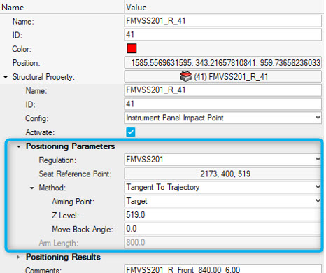
Positioning Methods
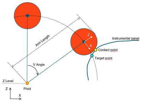
Tangent to Trajectory
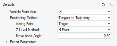
Selecting this method positions the headform with the target location on the circular trajectory of the center of the head.
The Aiming Point can be either Target or Contact point.
The Z Level Method fixes the Z coordinate of the pivot of the headform. Per default, it is set to the H-Point Z coordinate (= Seat Reference Point Z coordinate in the Design Point metadata). It can be switched to User defined, and you can provide a value.
The Move back Angle is applied once the impactor position is calculated in order to avoid intersections with the instrumental panel.
The metadata defined in the selected Design Point entity is ignored and overwritten with the values calculated by this positioning method.
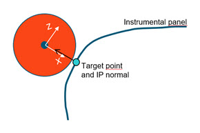
Normal to Trajectory
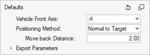
Selecting this method positions the headform with the IP-normal at target location aligned on the X-Axis of the coordinate system at the center of the headform.
The IP-normal vector is determined with the surrounding elements at the target location.
A pivot node selection is not requested.
The Move back Distance is applied once the impactor position is calculated in order to avoid intersections with the instrumental panel.
The metadata defined in the selected Design Point entity is ignored and overwritten with the values calculated by this positioning method.
Pivot/Angles
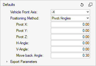
Selecting this method positions the headform by moving the pendulum pivot to the given (Pivot X, Pivot Y, Pivot Z) location, and applying successively the V-Angle around the global Y axis and H-Angle around the transformed X-Axis. (X’)
The Move back Angle is applied once the impactor position is calculated in order to avoid intersections with the instrumental panel.
Since pivot and angles are directly given as input, the target point may not necessarily be on the trajectory of the headform.
The metadata defined in the selected Design Point entity is ignored and overwritten.
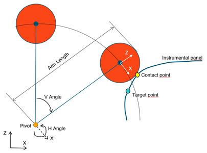
Target/Angles
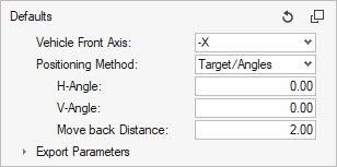
Selecting this method positions the headform by applying the H and V angles around the Target point location.
The pivot location is not an input and results from the application of both angles.
The Move back Distance is applied once the impactor position is calculated in order to avoid intersections with the instrumental panel.
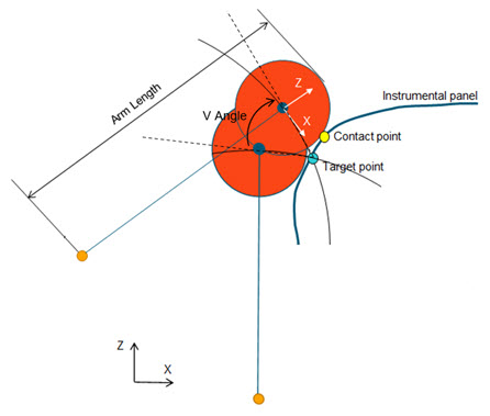
Automatic
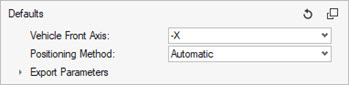
Selecting this method positions the headform according to the positioning parameters defined in the Design Point entity.
Export Solver Decks
This tool enables you to export ready-to-run solver decks for all the impact locations.
In the IP Positioning Workflow, provide the information in the Export Parameters.
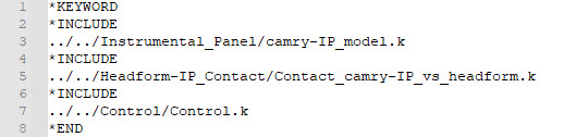
The Main File is the user-defined main input deck containing the include structure of the final model (IP model, contacts, controls, boundary conditions, …)
Here is an example of a Main File for LS-DYNA:
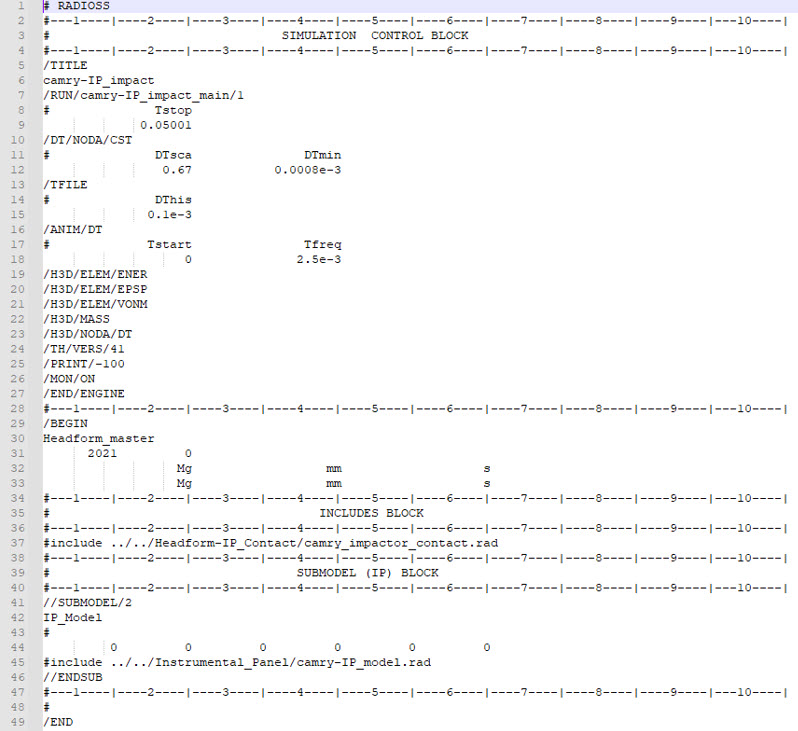
And here is an example for Radioss:
Headform File should point to the headform model that the tool will define as an include in the Main File during the export of the decks.
The Output Directory is the location where all the solver decks for each impact location are written out.
During the export process, the tool generates an additional include file containing the transformations to apply on the impactor using the Transformation Type.
Example of positioning include file generated by the tool:
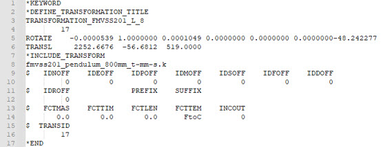

Finally, the positioning file is automatically added as an include file in the Main File. The resulting model files for each impact location look as follows:
- FMVSS201_L_8.k
- fmvss201_pendulum_800mm_t-mm-s.k
- Positioning_FMVSS201_L_8.key
- fmvss201_pendulum_800mm_t-mm-s.rad
- FMVSS201_R_12_0000.rad
- Positioning_FMVSS201_R_12_0000.rad