Connector Optimization
In this tutorial, you will learn how to perform an optimization to the number of connectors (welds) in a model, constrained by displacement values for two load cases.
Before you begin, copy the file(s) used in this tutorial to your working directory:
Open the Model
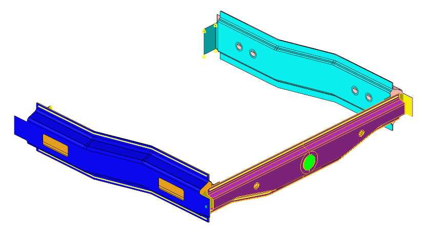
Figure 1.
Create an Exploration
-
From the Design Explorer ribbon, Exploration tool group, click the
Create Explorations tool.

Figure 2.The Explorations dialog opens. -
Click
 then select Optimization.
-
In the Study Path field, browse to and select the folder to store your
Optimization.
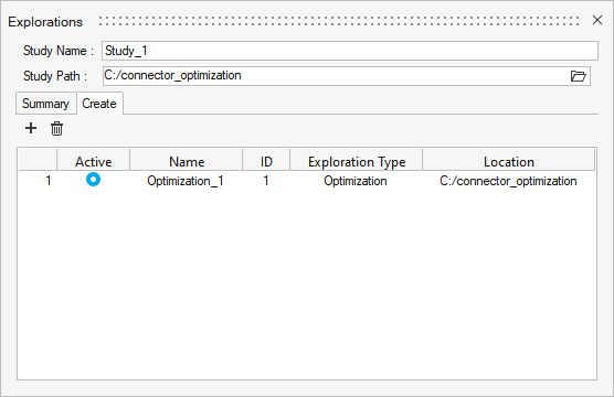
Figure 3. -
From the Exploration tool group, click the Design
Explorer tool.

Figure 4.The Design Explorer browser opens. You can see the newly created optimization exploration. Additional exploration entities will appear here as well.
Create Design Variables
-
From the Design Explorer ribbon, click the Connectors
tool.

Figure 5. -
Create connector inputs based on connector properties (attributes).
-
In the microdialog, select
 Discrete.
-
Click
 .
The Design Variable Values dialog opens.
.
The Design Variable Values dialog opens. -
Add three more rows and define the Upper Bounds as shown in Figure 6.
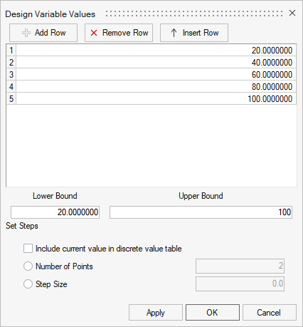
Figure 6. -
From the guide bar, click
 .
.
-
Click
 .
.
-
In the microdialog, select
-
From the Design Explorer ribbon, Connectors tool group, click the
Review tool.

Figure 7.The Inputs dialog opens. -
Review the design variables.
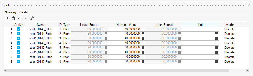
Figure 8.
Create the Exploration Responses
-
From the Design Explorer ribbon, click the Disps.
tool.

Figure 9. -
Create a displacement response.
-
From the guide bar, click
 .
The Advanced Selection dialog opens.
.
The Advanced Selection dialog opens. -
In the microdialog, click
 .
.
-
Click .
The Advanced Selection dialog opens.
-
Click .
-
Click .
The Entity Editor dialog opens.
-
From the guide bar, click .
-
From the guide bar, click
-
Create another displacement response.
-
From the guide bar, click .
The Advanced Selection dialog opens.
-
In the microdialog, click .
The Entity Editor dialog opens.
-
Click the Loadcase Id field and click .
The Advanced Selection dialog opens.
-
From the guide bar, click .
-
From the guide bar, click
-
Create connector response.
-
From the Design Explorer ribbon, click the
Connector tool.

Figure 10. -
From the guide bar, click .
-
Click .
-
From the Design Explorer ribbon, click the
Connector tool.
Create Goals
In this step, you will create one objective and two constraints.
-
Create an objective.
-
From the Design Explorer ribbon, click the
Objectives tool.

Figure 11. -
From the guide bar, click .
The Advanced Selection dialog opens.
-
From the guide bar, click .
-
From the Design Explorer ribbon, click the
Objectives tool.
-
Create a constraint.
-
From the Design Explorer ribbon, click the
Constraints tool.

Figure 12. -
From the guide bar, click .
-
From the guide bar, click .
-
From the Design Explorer ribbon, click the
Constraints tool.
-
From the guide bar, click .
Evaluate the Optimization
-
From the Design Exploration ribbon, Evaluate tool group, click the
Evaluate tool.

Figure 13.The Evaluate dialog opens.
Review the Optimization
-
From the Design Exploration ribbon, Evaluate tool group, click the
Results Explorer tool.

Figure 14.The Results Explorer opens. -
Review the optimal run/results, weld pitch values, and resulting response
values in the Summary tab.
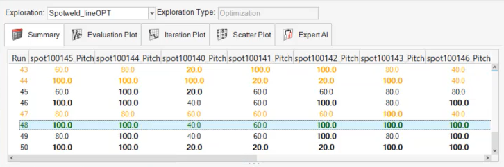
Figure 15.