Hex Meshing
Use the Hex tool to create a mesh of solid elements.
While the Solid Map tool can automatically create 3D mesh directly on solids as long as the solids you select are already mappable, hex meshing depends on an existing 2D mesh, which is then extrapolated into a 3D mesh based on the parameters you input.
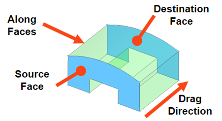
Figure 1.
- Two opposing faces are called "Source" and "Target" faces.
- One or more faces that directly connect and enclose the volume between the source and target are called "Guide" faces.
- The drag direction is the vector from the source face to the destination face.
Create Hex Mesh
-
From the 3D ribbon, click the Hex tool.

Figure 2. -
Click
 on the guide bar to set
parameters for meshing.
Set the element size or density to be defined in the along direction. This determines the number of elements along the depth of the mapping.The biasing style works in conjunction with biasing intensity. If intensity is "0", biasing is not applied.
on the guide bar to set
parameters for meshing.
Set the element size or density to be defined in the along direction. This determines the number of elements along the depth of the mapping.The biasing style works in conjunction with biasing intensity. If intensity is "0", biasing is not applied.
Figure 3. No biasing
Figure 4. Linear
Figure 5. Bell Curve
Figure 6. ExponentialThe following advanced options are available.- Apply orthogonally along extrusion
- Keep the solid elements generated more perpendicular to the surface faces in the along direction
- Optimize hex elements
- Optimization is performed to improve Jacobian and warpage quality. Avoids negative Jaobian elements.
-
Create hex mesh in one of the following ways:
Option Description Along vector - In the microdialog, set a density value or an element size if not already defined in the options menu.
- Enter a thickness value or drag the manipulator to create hex
mesh along the element normal.Tip:
- Click
 to pick the global X/Y/Z,
screen normal, screen parallel, and/or a
user-defined direction instead.
to pick the global X/Y/Z,
screen normal, screen parallel, and/or a
user-defined direction instead. - Click
 to flip the normal
direction.
to flip the normal
direction.
- Click
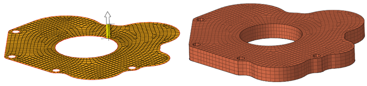
Figure 7.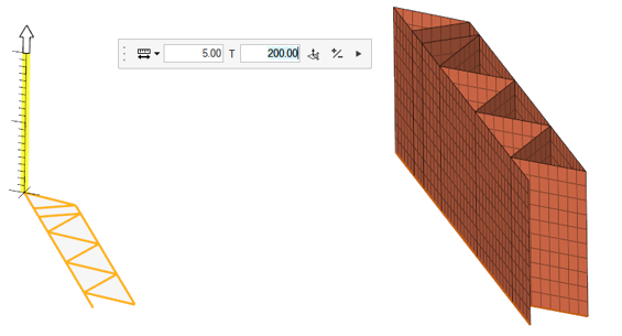
Figure 8. . 1D elements converted to 2D elements along a vector.With Guides/Targets (Optional) - Click the Guides selector.
- Select the geometry that defines the face of the 3D volume along
which you wish to map the mesh.
When elements are used, the mapped mesh maintains the nodal positions with selected elements. They can be equivalenced to have common nodes. While selecting nodes, each selection should represent an edge that connects the source and destination.
- Click the Target selector.
- If desired, select geometry that you wish the 3D mesh to match
up with.
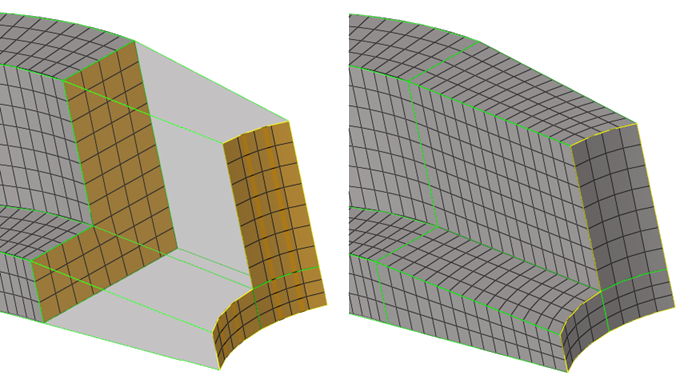
Figure 9. - In the microdialog, set a density value or an element size if not already defined in the options menu.
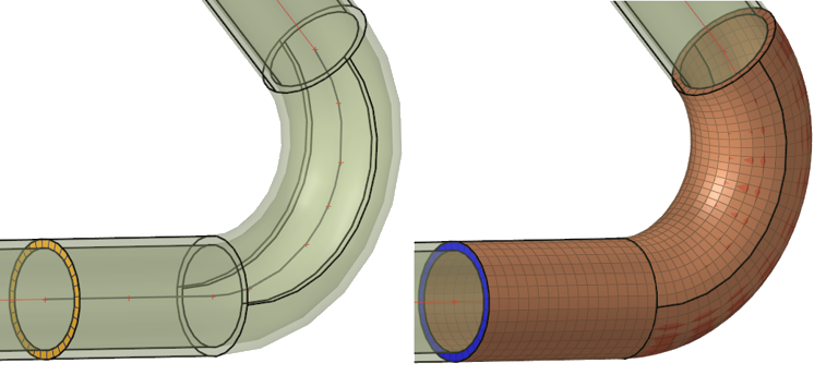 Figure 10. . Mesh created with source elements and a midline as a
guide.
Figure 10. . Mesh created with source elements and a midline as a
guide.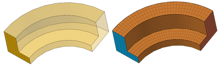 Figure 11. . Mesh created with source elements and surfaces/lines as
guides.
Figure 11. . Mesh created with source elements and surfaces/lines as
guides.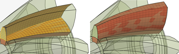 Figure 12. . Mesh created with source elements and multiple faces and
elements as guides. Topo(2D/3D) element faces are
supported.
Figure 12. . Mesh created with source elements and multiple faces and
elements as guides. Topo(2D/3D) element faces are
supported.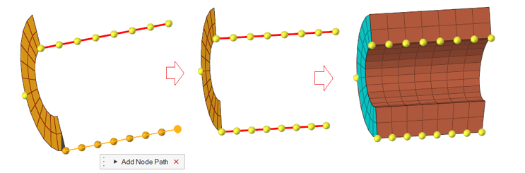 Figure 13. . Mesh created with source elements and multiple node paths as
guides.
Figure 13. . Mesh created with source elements and multiple node paths as
guides.
HyperMesh displays the progress of the solid map meshing process in the status bar. Upon completion, HyperMesh displays a report of the mesh quality. The element quality value reported is the worst scaled Jacobian in the mesh. The scaled Jacobian's value may range from 0.0 to 1.0(best). An elem's scaled Jacobian is a ratio of the elem Jacobian over the Jacobian of an ideal elem of the same configuration.