Create Thin Solid Mesh
Use the Thin Solids tool to create 3D mesh on thin solids. The mesh is created by first generating a 2D mesh on a selected set of source faces, and then extruding this mesh to generate solid hexa or wedge elements.
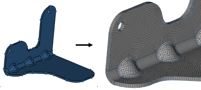
In order to create a thin solid mesh, the solid geometry must meet a certain criteria.
- The solid entity should be a sheet metal solid. The thickness should be less than other the two dimensions (length and width).
- You should be able to identify both the Source (start) faces and the Target faces.
- Source and destination faces must be connected by side (along) faces which are almost 90 degrees to them.
-
From the 3D ribbon, click the Thin
Solids tool.
Figure 2. 
- Optional:
On the guide bar, click
 to define meshing options.
Important: There are two types of mesher provided: one is BatchMesher and the second is Freeform. In the case of BatchMesher, element size, type, and so on used from Param/Criteria, it is important to use the appropriate param/criteria settings.
to define meshing options.
Important: There are two types of mesher provided: one is BatchMesher and the second is Freeform. In the case of BatchMesher, element size, type, and so on used from Param/Criteria, it is important to use the appropriate param/criteria settings. -
Select thin solids in the following ways:
- Click Find on the guide bar to automatically check for and select all thin solids.
- Manually select each thin solid.
By default, the source and target surfaces for each solid are also selected. These represent the "beginning" and the "ending" surfaces that define the direction of the mesh mapping - Optional: Uncheck the Auto detect source and target option to manually define any source and target hint surfaces.
-
Adjust the mesh size in the microdialog if needed then
click Mesh.
Tip: If you’d like to have biasing along the mesh direction, you need to select the biasing method and set up the appropriate parameters.The biasing affects element growth in successive layers, moving away from the source faces.
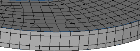
- No Biasing
- All layers are equal in thickness.
Figure 3. Example: No Biasing 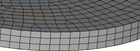
- Exponential Biasing
- Successive layers are exponentially thicker.
Figure 4. Example: Exponential Biasing 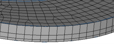
- Bellcurve Biasing
- Layers are progressively thicker near the center, but
thinner near the source and destination faces.
Figure 5. Example: Bellcurve Biasing