Adjust Normals
Use the Normals tool to reverse the normals of shell elements or surfaces. The orientation of unassociated shell elements or FE geometry can also be adjusted. The normal of an element is determined by following the order of nodes of the element using the right-hand rule.
-
From the 2D ribbon, click the Normals tool.
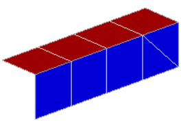
Figure 2. 
-
From the guide bar, choose an operation to
perform.
Option Action Reverse - Select Reverse to reverse the normals of selected surfaces/unassociated mesh.
Note:- Elements associated to FE geometry cannot be selected.
- Surfaces (CAD and FE geometry) can be selected.
- Changing normals of a surface also changes the normals of its associated elements.
Adjust - Select Adjust to adjust the normals of selected FE geometry surfaces/ mesh associated to CAD geometry/unassociated mesh.
- Optionally, click
 and select the
Adjust FE associated to CAD surfaces
check box from the Options menu to select CAD surfaces and
change the associated elements normals as per the selected CAD
surfaces.
and select the
Adjust FE associated to CAD surfaces
check box from the Options menu to select CAD surfaces and
change the associated elements normals as per the selected CAD
surfaces. - Optionally, select an orientation method for adjusting normals.
- Auto select.
- Select the Auto check box.
- Click and select
and define Use feature angle to
specify feature angle.
For each connected section, the normals are adjusted for all elements in that section to be consistent with the dominant normal direction already existing within that section, with the sections defined based on the specified feature angle.
- Adjust the normals for all elements to be consistent with the dominant normal direction that exists within each connected section.
- Select element.
- Clear the Auto check box.
- Select Elements.
- Adjust the normals for all elements to be consistent with the reference element.
- Select direction.
- Clear the Auto check box.
- Select Direction.
- Using the Vector tool, define the direction in the
modeling window.
Learn more about the Vector tool in Define Orientation.
- Adjust the normals for selected elements to best align with the specified vector direction.
-
On the guide bar, complete one of the following:
- Click
 to apply and stay in the tool.
 - Click
 to apply and close the tool.
 - Click
 to exit the tool without applying.
- Click