Imprint
Use the Imprint tool to imprint geometry or mesh onto target surface/lines or elements creating new edges/fixed points or a mesh patch respectively.
Imprinting points on lines or surfaces creates geometry vertices similar to using the Split: Interactive tool. Imprinting surfaces onto surfaces imprints all of the source surfaces' edges onto the target surfaces.
Imprinting node list obeys post imprint options of FE tab in  .
.
.Note: Node list/elements imprint to
CAD surface is not possible.
Imprinting elements / FE geometry to elements / FE geometry obeys post
imprint options of FE tab in .
-
From the 2D ribbon, click the Imprint tool.
Figure 1. 
-
Select source to imprint.
- On the guide bar, activate the Source selector and choose whether to imprint lines, nodes, node list, points, surfaces, or elements using the drop-down menu.
- Make your selection in the modeling window.
-
Select imprint targets.
- Optional:
On the guide bar, click
to define imprint options.
- Click Preferences to define CAD/FE topology revision options.
- Select the FE tab to expose additional options related to FE geometry.
- From the FE tab, select Topology color mode to change the face color mode to topology
- Optional:
Use the microdialog to define the direction on
imprint.
Restriction: This is only available for mesh imprinting to target FE geometry or elements.
-
On the guide bar, select the Use
anchors check box to select the nodes to be fixed in the
destination mesh during mesh imprint.
Restriction: This is only available for mesh imprinting to target FE geometry or elements.
- Click Imprint.
Tip:
- Split multiple surfaces with multiple lines at once.
- Use the Split: Interactive tool to untrim previously imprinted surfaces.
- Use the Stitch tool to suppress imprinted edges.
CAD Options
- Maximum imprint distance
- Use maximum imprint distance between source and target geometry.
- Maximum distance
- Enter an imprint distance.
- Line extension method
- Select a line extension option.
- Keep line endpoints
- Keep line endpoints when extending lines.
- Surface imprint method
- Select which lines to imprint.
- Do not imprint internal edges
- Skip internal edges and common edges of selected surfaces.
- Do not imprint near existing edges
- Skip edges too close to pre-existing features.
FE Geometry Options
- Maximum imprint distance
- Use maximum imprint distance between source and target geometry.
- Maximum distance
- Enter an imprint distance.
- Post imprint options
-
- None
- Simple method to imprint source on target surface.
Figure 2. 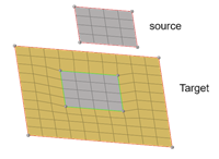
- Create patch between imprinted edges
-
Figure 3. 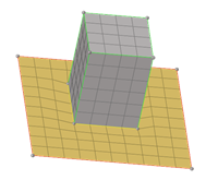
- Move target imprint edges to source
-
Figure 4. 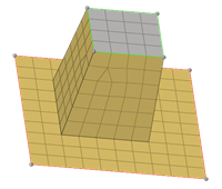
- Move source to target
-
Figure 5. 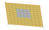
- Create elements in
- Select to create imprint or patch elements in the following:
- Source component
- Current component
- Destination component
- Do not remesh/rebuild extension
- Use to avoid remesh or rebuild of the patch elements.
Figure 6. 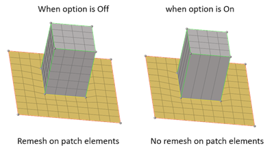
- Closed loop for node list selection
- Use to close the loop of selected node list.
Figure 7. 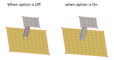
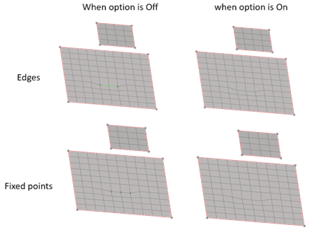
- Do not add fixed points/edges on nodes imprint
- Use to imprint nodes on FE geometry without fixed points or edges.
Figure 8.