Wizards
Wizards offer an easy and convenient way to assemble and analyze models comprising of systems stored in a library with few clicks.
The Assembly Wizard helps to assemble a model by selecting the combination of required systems. The Task Wizard helps to attach an analysis or an event to the model assembled using the Assembly Wizard.
Accessing the Wizards
Assembly Wizard
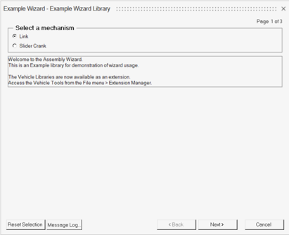
Upon finish, the selected systems are imported into an empty MotionView session.
Once the systems are imported, the model can be further edited like any other regular MotionView model. Upon saving, the wizard choices are saved to the MDL.
Add an Analysis
Wizard Path
Refer to Register the Wizard Files described later in this section.
Example Wizard
The following section describes the general process that can be followed to create one’s own wizard library considering the models in the Example Wizard.
Create Your Own Wizard Library
- Capture product and testing knowledge into a library of systems and analyses.
- Offers ease of assembling model variants to a large group of users.
- Provides easy customization of assembling models with very minimal knowledge of programming.
- Saves repetition of model building with the same topology.
Steps to Create a Wizard Library
- Build model/s and events.
- The model could be built interactively using the graphical user interface and/or editing the MDL in a text editor. Familiarity with the MDL language would be useful.
- While building the model, organize the model into hierarchical systems.
- It is recommended to create the systems in a modular way. That means, each system is self-contained. Any reference to an entity external to the system is managed through Attachments.
- Define parametric relations between entities as necessary. It is beneficial to create either a dataset or a set of data members at the system level that comprise of datatypes - Real, Integer, Boolean, Options, Strings and Filenames. These data members can form the key parameters that configure a system without the need to edit the child entities of the system.
- A Form can be used to organize the data members in a row-column tabular form. Forms also support adding an image that can describe the system parameters.
- Similarly, organize events or test cases applied to the model into Analyses.
- Solve the model and create plots and animations as needed. Save the session to a Report template (*.tpl).
- Save the system and analyses definitions individually
to form a library with a directory.
- Systems and Analyses can be exported into an MDL definition.
- Include data during export. They will form as the default values for the entity properties.
- Author the Assembly wizard file that contains the model building logic using the MDL wizard language.
- Author the Task wizard file that contains the events or analyses associated with the models using the MDL Wizard Language.
- Register the wizard files using the preference file statements to link with the Wizard dialog.
These steps are well elaborated further using the Example Wizard.
Build Model/s and Events
- Link Model
- The following image shows the system arrangement of the Link model.
Figure 8. Link Model 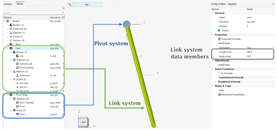
The model is arranged in two systems: Link system and Pivot system.
Link system consists of:- Data members Length and Angle (added using the Properties section in the Entity Editor).
- Point link end1 is an independent point.
- Marker Reference at point link end1. Its orientation is free.
- Point link end2 is defined in cylindrical coordinates in the Reference marker frame with the Length and Angle as parameters using the loc_cylindrical function. The point is located on the XY plane of the marker.
- Point link CG is a point between points link end1 and link end2.
- Body link.
- Graphic Cylinder Link for the body link defined between end points.
- Graphic End 2 Cylinder at link end 2.
Pivot System
The purpose for the pivot system is to constrain the link to Ground Body at one of the ends. It is desired to provide more than one variation (hinge or ball) to the pivot system while assembling the link model using the wizard.- Pivot Hinge
- In this system, the link will be constrained using a
revolute joint at the Reference marker origin and
oriented along its Z axis. Since the link body and
Reference marker are in a different system (link), to
maintain modularity, these entities are input to the
pivot system as attachments.
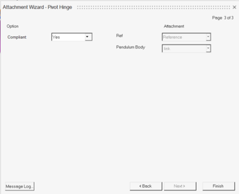
Figure 9. Link Model - Pivot System (Hinge) 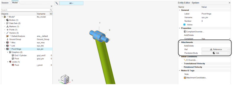
The system consists of:- Attachments – Ref (Marker) and Pendulum Body (Body).
- Joint Pivot – Revolute
joint between the attachment Pendulum
Body & Ground Body at
Ref marker’s origin along
Ref marker's Z axis.Note: Origin and alignment axis must be resolved using Advanced selection to refer to the attachment’s child attributes.
- Graphics for the joint – graphic’s body, origin and direction refer to the joint Pivot attributes.
- Pivot Ball
- The pivot ball is similarly constructed as the hinge
system above, except the type of joint used is a Ball
joint instead of revolute. The system can either be
created in the same model or a separate model can be
created.
Figure 10. Link Model - Pivot System (Ball) 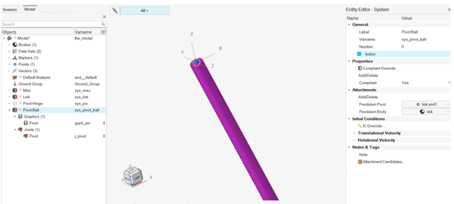
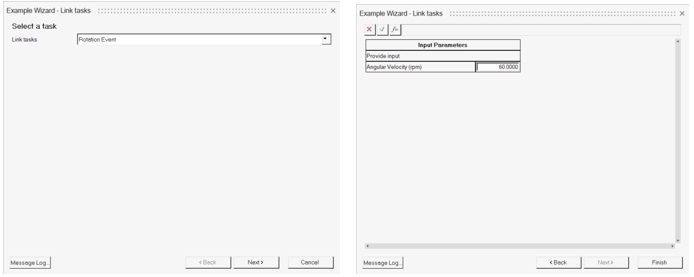
Analyses- Rotation Analysis
- Imposes a constant velocity motion on the revolute joint
of the Pivot Hinge. When building the wizard, this
analysis will only be available when the Pivot system is
of type Hinge.
Figure 11. Link Model - Rotation Analysis 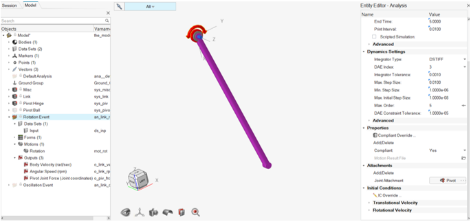
The analysis contains:- Attachment Joint Attachment to apply motion.
- Dataset Input for speed of rotation.
- Form that links to the dataset (Form can be added by editing the MDL).
- Motion Rotation. The value
in the Input dataset is parametrically linked
here.
Figure 12. 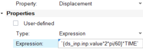
- Outputs.
- Report – A report that plots the rotation speed in HyperGraph and animates the results in HyperView. The report refers to a definition in a report template and can be created by the following method.
Solve the model and create plots and animation on a separate page in the session.Figure 13. Results Plot for Rotation Analysis 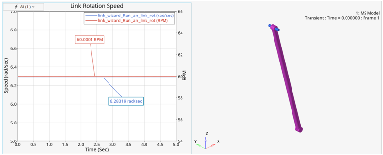
Save the session () as a report template.
Insert a *Report statement in the analysis definition block of the model MDL using a text editor. For every solver run, the report is accessible through dialog in the Analyze ribbon.- Oscillation Analysis
- Adds an extra mass to the link and lets the link
oscillate under gravity.
Figure 14. Link Model - Oscillation Analysis 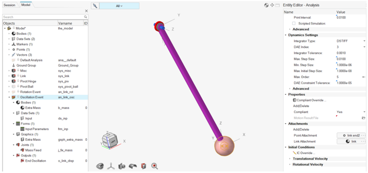
This analysis contains:- Attachment Point Attachment and Link Attachment (Body) to add extra mass at the link end.
- Body and Graphics Extra mass.
- Dataset Input for mass of Extra Mass.
- Form that links to the dataset (Form can be added by editing the MDL).
- Output to measure oscillation.
- Report – A report definition that plots the oscillation of the mass in HyperGraph and animates the results in HyperView.
- Slider Crank Model
- The slider crank model is also built following the same process above.
The model is arranged in two systems.Slider Crank System consists of:
- Dataset Cyl_configuration with data members Crank_ang_about_Global_X, Crank_length, Conrod_length, and Piston_dia.
- Bodies – Piston, ConnectingRod and Crank with graphics.
- Points to define graphics on bodies. The points are parametrically linked to the dataset members.
- Joints.
- Marker Combustion_ref on piston to apply force on Piston.
- Solver variable Crank Angle to measure the crank angle between 0 and 720 deg.
- Outputs.
Flywheel system consists of:Figure 15. Slider Crank Model 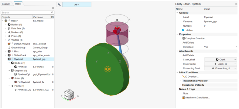
- Attachments – Crank_shaft, Crank Center, and Connecting Point.
- Flywheel body with graphic.
- Joint – Fixed to Crank_shaft at Connecting Point.
- Flywheel CG at Crank_shaft.
- Analysis – Force on slider
-
Figure 16. Slider Crank Model - Analysis Force on Slider 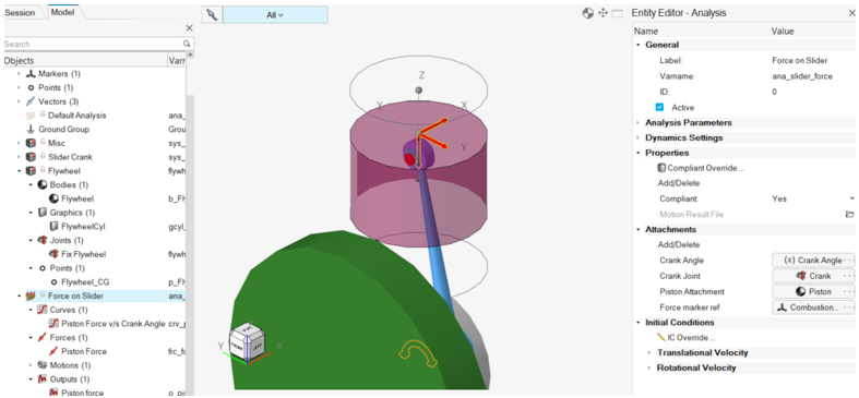
- Attachments – Crank Angle (SolverVariable), Crank Joint (Joint), Piston Attachment (Body), Force marker ref (Marker).
- Curve – Piston Force v/s Crank Angle.
- Piston Force – on Piston Attachment at Force marker ref-origin. Force is applied using the Curve Piston Force v/s Crank Angle with Crank Angle as the independent variable.
- Motion – Rotational Velocity Motion on Crank Joint.
- Output – Piston force on Piston Attachment.
- Report – A report that plots the Force on the piston against the Crank Angle along with an animation window by the side.
Figure 17. Results Plot for Force on Slider 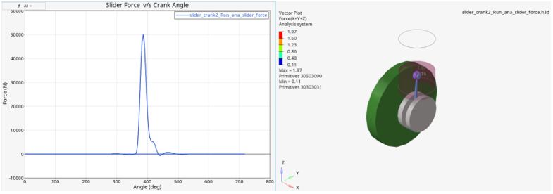
Saving System and Analyses Definitions into a Library
- Selecting the systems (or analysis) individually in the browser and use the option.
OR
- Copy the *DefineSystem() (or *DefineAnalysis) - *EndDefine() blocks into a separate file and saving it to an mdl file. Any reference by an entity in the system to another definition may also require definition block such as *DefineGraphic() or *DefineDataset() to be copied.
Also copy the report tpl files referred to by *Report into the library. Ensure that the path in the *Report is in relation to the analysis definition file. The files associated with the Example Wizard are located at ~install\hwdesktop\hw\mdl\mdllib\Example_wizard.
Author the Assembly Wizard File
- Each panel that appears with options such as radio buttons or drop-down choices are defined within a *BeginPanel() - *EndPanel() block.
- *Title() can be used to specify a title for the panel.
- *BeginRadioGroup() - *EndGroup() defines a radio choice within the
panel.
Figure 18. Assembly Wizard Statements to Dialog Mapping 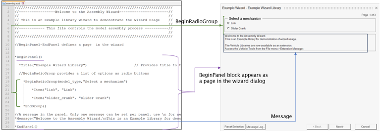
- Use the *if-elseif-else-endif() block to branch out further system selection
based on previous radio or system selections.
Figure 19. Assembly Wizard Statements to Dialog Mapping - Conditional Branching 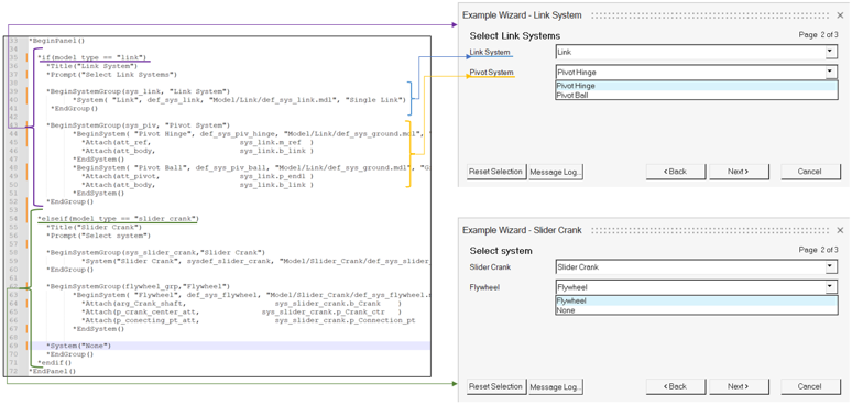
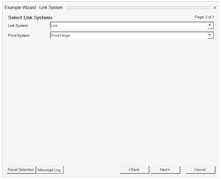
- *BeginSystemGroup() - *EndGroup() is used to define a system selection
choice. This appears as a drop-down option in the dialog.
- *BeginSystem() - *EndSystem() block offers a choice of system
selection. There could be more than one such block within the
group.
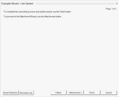
- *Attach offers attachment choice. An attachment to a system may have several attachment choices. These choices will appear in the Attachment Wizard. If Attachment Wizard is not accessed, the first in the list of *Attach choices for an attachment will be considered as default.
- *System can be used to instantiate a system which does not have any attachments.
- *System(“None”) can also be a choice of “No system”.
- *BeginSystem() - *EndSystem() block offers a choice of system
selection. There could be more than one such block within the
group.
- *Message can be used to have a message at the bottom of the panel.
- Only one *Message is allowed on a panel.
- Message should appear in a single line entry. Use /n to display the message in multiple lines in the dialog.
The wizard can contain several BeginPanel blocks. At the finish, MotionView will instantiate the systems that are selected under each panel. It will also resolve the attachments.
The wizard selection choices are also saved in the model file.
Author the Task Wizard File
- The tasks are listed using *BeginTaskGroup() within one *BeginPanel() block.
- Use *if-elseif-else-endif block to customize the task group based on model
or system selections. The if block can also be used within *BeginTaskGroup()
to customize the tasks.
Figure 20. Task Wizard Statements to Dialog Mapping 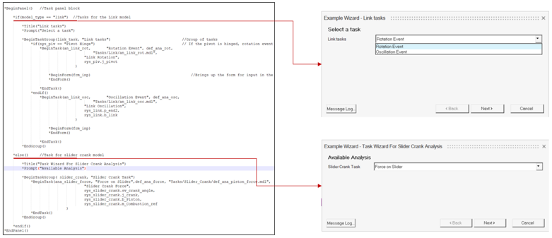
- Each task is defined using a *BeginTask() block that refers to an analysis definition within a definition file (mdl). Attachments to the analysis are also passed as arguments in this block.
- A *BeginForm() can be used to bring up a form that is defined in the
analysis once clicking Finish.
Figure 21. Form in Task Wizard 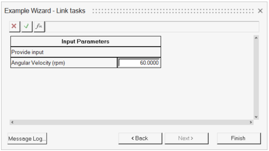
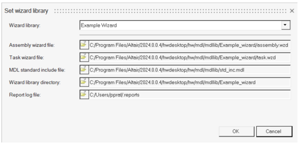
Register the Wizard Files
Once all the system definitions and wizard files are ready, it is time to register the wizard files, so that the wizards can be invoked through the graphical user interface.
| Assembly Wizard file | File containing Assembly Wizard code in the MDL Wizard language. |
| Task Wizard file | File containing Task Wizard code in the MDL Wizard language. |
| MDL standard include file | This file is read at the start up of MotionView. This file can contain any model defaults in the MDL language. It is recommended to use the std_inc.mdl which is part of standard include. If any additional defaults have to be provided, please include the std_inc.mdl using the *Include() statement and then followed by other statements. |
| Wizard library directory | Folder containing the system, analysis, report and any other reference files used in the wizards. |
| Report log file | Reports in the model are logged during the runs and are stored in this file. Information from this file appears in the dialog in the Analyze ribbon that can be used to plot automated reports for the run. |
- User/Custom library – in the
 Settings dialog of the Wizard group in the Assembly
ribbon.
Settings dialog of the Wizard group in the Assembly
ribbon.Figure 22. Wizard Settings 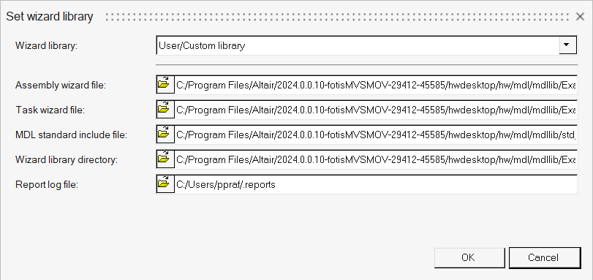
This option allows registering only one library.
- Using Preference file statements
Use a preference file (*.mvw).
The preference file can be registered and loaded from the menu .
The file can contain statements as shown below:*Id("MotionView v12.0") *BeginDefaults() *BeginModelDefaults() *BeginMdlDefaults() *RegisterAssemblyWizardFile(MyLibrary,"C:/Libraries/My_Library/assembly.wzd" ) *RegisterTaskWizardFile(MyLibrary, "C:/Libraries/My_Library/task.wzd" ) *RegisterWizardLibDir(MyLibrary, "C:/Libraries/My_Library/" ) *RegisterMdlStdIncFile(MyLibrary,getenv("ALTAIR_HOME")+"/hw/mdl/mdllib/std_inc.mdl"} ) *RegisterReportsLog(MyLibrary,"C:/Users/username/Documents/report.log") *EndMdlDefaults() *EndModelDefaults() *EndDefaults()The first argument in the *Register statement refers to the name of the library. More than one library can be registered using one or more preference files.
See Preference Files for additional information.