Create and Edit Analyses
In MotionView, an analysis is a container entity that can contain collections of the loads, motions, and entities including bodies and graphics that describe the event to be simulated for a model. A model can contain any number of analyses but only one analysis can be active at a given instance. When a model is run in MotionView, a particular analysis is selected and MotionView includes the loads and motions described in the analysis when it submits the model to the solver.
An analysis is represented by the following characteristics:
- An analysis can be added only to the root system Model.
- It can contain any other modeling entities like points, bodies, joints, forces, and so on.
- An analysis can have a system as its child entity.
- Only one analysis can be a active at a given instance. The Analysis settings (Run icon in the Analyze ribbon) and Export Solver Deck pre-selects the active analysis.
- The analysis takes attachments in a similar way as systems and assemblies.
- Simulation type and settings can be edited for any analysis in the analysis’ Entity Editor.
- A Default Analysis (ana__default) is available in the model. No new entities can be added to this analysis. However, the simulation type and settings can be edited.
Similar to an assembly, which is an extended version of systems, the analysis container entity is also extended to have a distributed file approach. However, the extension is contained within the same entity called "Analysis". The analysis container comes in two variations:
Inline Analysis
In this type of analysis, the definition and properties are saved inline within the model MDL file.
- In MDL, an inline analysis is created by instantiating a definition using the *Analysis statement that refers to a *DefineAnalysis block.
Distributed Analysis
This refers to the distributed files based analysis, similar to an assembly entity. This type of analysis works on a similar concept as assemblies with some rules and exceptions:
- Distributed analysis refers to a data file and data file subsequently refers to a definition file.
- An assembly can be added to a distributed analysis, but not to an inline analysis.
- Unlike assemblies, a placeholder for a distributed analysis is not available.
- A distributed analysis has a ALLOWED_MODEL_TYPE attribute that can be used to restrict the application of the analysis for a particular type of model.
- In MDL, a distributed analysis is instantiated using the *BeginAnalysis block. This block has a *DataInclude statement that refers to a data file. The data file contains a *BeginAnalysisDataFile block that has *DefinitionInclude that refers to a definition file. The definition file holds *BeginDefinitionFile that contains the *DefineAnalysis block. This structure is consistent with that of the assembly entity.
Example
The following simple example model demonstrates the concept of an analysis. This model is available at ~hw_install/demos/mv_hv_hg/modeling/container_entities/system_analysis/door.mdl. The model has been arranged into a system called hatchback system, which in turn has two child systems; the door system and the damper system. The images below show a simplified model of a hatchback door of a car with the model MDL file shown alongside.
One analysis is a kinematic analysis, which is accomplished by adding a motion to the hinge joint in the door system.
Another analysis is a dynamic analysis, which is accomplished by applying a force at the end of the door. These two events are exclusive. For example, the motion of the hinge joint is not applied when the force is applied and vice-versa.
- The entire model information is contained within a *BeginMDL - *EndMDL block in the door.mdl (model file).
- Apart from the two system instances and their definition block, the model
contains an *Analysis statement that instantiates the
kinematic analysis (ana_kin). This analysis instance
refers to the analysis definition (def_ana_kin) within
the *DefineAnalysis block in the model file.
- The door hinge joint from the door system is passed as an attachment to the analysis. A motion is defined that uses this attachment.
- The data related to the motion is within the *BeginContext
(ana_kin) block.
Figure 1. 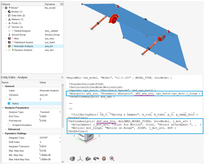
- The model file also contains a *BeginAnalysis block that
instantiates the dynamic analysis.
- This block refers to the data file (dyn_data.mdl) which in turn refers to the definition file (dyn_def.mdl).
- The door body and the center end point at the door are passed as attachments to this analysis. A force entity is defined that uses these attachments.
- The force data is contained in the data file.
- The MDL structure is similar to that of the assembly. The data is
contained within *BeginAnalysisDataFile. The
analysis definition block *DefineAnalysis in the
definition file is contained within
*BeginAnalysisDataFile.
Figure 2. 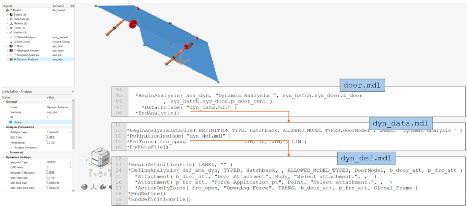
- The *SetActiveAnalysis statement controls which analysis is active.
Add an Inline Analysis
-
Go to the Assembly ribbon and click on the
Analysis icon within the Arrange group.
OR
Right-click on the Model label and select .
The Add Analysis dialog is displayed. - Select the Inlined in model file option and click Next.
- Assign a variable name to the analysis.
- Assign a label to the analysis.
- Assign a definition name to the analysis.
- Click Apply to add the analysis and continue adding more analyses. Click Back to change the type of analysis being added. Click OK to close the window and finish adding the analysis.
Add a Distributed File Analysis
-
Go to the Assembly ribbon and click on the
Analysis icon within the Arrange group.
OR
Right-click on the Model label and select .
The Add Analysis dialog is displayed. - From the Add Analysis dialog, select the Uses data and definition files option and click Next.
-
Choose either of the following options and click
Next:
- Assign a variable name to the analysis.
- Assign a label to the analysis.
- Assign a definition name to the analysis.
- Click Apply to add the analysis and continue adding more analyses. Click Back to change the type of analysis being added. Click OK to close the window and finish adding the analysis.
Edit an Analysis
Modify attachments, set initial conditions, define options, and import/export the analysis.
-
Each analysis has a list of attachments that connect it to other systems or
assemblies on the Attachments tab. To add or delete an attachment.
-
To modify the entity resolved into an attachment or resolve an Unresolved
attachment, select the attachment in the Entity Editor.
-
The entity collector is now active for picking. Pick the entity using
the modeling window or Use the Advanced
Selection by clicking on ellipses
 at the right end of the collector.
-
The entity collector is now active for picking. Pick the entity using
the modeling window or Use the Advanced
Selection by clicking on ellipses
-
Properties of Datamembers are listed under the
Properties section. A property can be created and linked to one or more entities
within the Analysis using parametric expressions. Property can be any of the
following data types: Real, Integer, Boolean, String, Option, or Filename. To
add or delete a property, click on Add/Delete:
-
Under the Initial Conditions section:
Specify Simulation Parameters
Each analysis contains Analysis parameters and other simulation parameter settings that can be set for the simulation run. Each analysis can have different analysis parameters and simulation settings. By default, these settings inherit values from the Global Simulation Settings.
-
Under Analysis Parameters, select the Analysis Type.
Based on the selected analysis type, other parameters and Settings will be
either active or inactive as applicable.
- For Transient, Quasi-Static or Static+Transient enter an End Time and Print Interval.
- Dynamic Settings lists parameters for a Transient run.
- Static Settings lists parameters for Static and Quasi-Static run.
- Linear Settings lists parameters for Linear run.
- Frequency Settings lists parameters for Frequency Response analysis.
Note: Description of parameters under each section is give in the Global Simulation Settings Dialog. -
Scripted Simulation – use this option if a simulation
script exists to run a simulation. A simulation script is created using a
Template of type “Write text to solver command file”. When this option is
selected, MotionView will ignore the simulation
mentioned in the Analysis Type while exporting a solver deck or during a
run.
Note: If this option is off while a simulation script exists, a simulate command is sent to the solver that corresponds to the Analysis type, in addition to the commands in the script.
Export an Inline Analysis
Analyses can be individually exported to an .mdl file by clicking . You can export the entire analysis, including the topology information to the file, or you can export only the model properties for reading into another model. Only inline analyses can be exported to a definition file.
- From the Model Browser, select the inline analysis to save.
-
Go to .
The Export Definition dialog is displayed.
-
Select a file name in Select File and click
Export.
The analysis is exported.
- Use the Export topology as: drop-down menu to specify entity definition statements and definition blocks (that define systems, datasets, templates, and so on).
- The Property Data options refers to *Set statements that assign values to the entity.
Import a Definition to an Analysis from a File
Systems can be imported into an Analysis from an .mdl file through the menu.
- From the Model Browser, select an analysis.
-
Go to File > Export > MDL Definition.
The Import Definition dialog is displayed.
- Select a file name in Select a definition file.
- Select the type of definition from the drop-down menu. All available definitions (definition name) in the file are listed below.
- Select a definition to be imported.
- Provide a Label, Variable name and descriptive note (optional).
-
Click OK.
Warning: If the name of the definition in the file being imported is already used in the current model, the definition will be imported with a new name. Any reference to the original definition may change to the already existed definition in the model.