Quality Feel (Static) Analysis
Use SnRD to identify squeak and rattle for Static load.
- Prepare the FE model for analyzing squeak and rattle issues.
- Apply a static load of amplitude -5.55 to the certain node(s) on Lower Control Panel component. This simulates a touch point scenario.
- Run analysis and post-process the results.
Choose the workflow according to your need and refer to sections mentioned above for the procedures. Once you have a model with E-Lines, you can proceed with the Static Loadcase Setup process.
Before you begin, copy the file(s) used in this tutorial to your working directory:
- Model file: tutorial_ip_snr_model.fem
- E-Line Databsae File: tutorial_ip_snr_model_pre_output.csv
Define Static Loadcase
In this step, you will create a Static loadcase.
-
From Setup group, select the drop-down arrow next to .
 Figure 1.
 -
From the graphics area, select the following nodes in the Lower Control Panel
component.
- 493552
- 493543
- 493563
- 493478
- 493477
- 493518
- 493503
- 493494
- 493530
 Figure 2.
 -
For the load direction, select X.
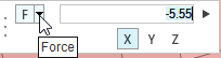 Figure 3.
 -
Click
 .
The Force loads at the selected nodes are created. The respective load collectors are created and listed in the Model Browser.
.
The Force loads at the selected nodes are created. The respective load collectors are created and listed in the Model Browser.
Define Constraint
In this step, you will define model constraints.
-
In the Setup ribbon, select .
 Figure 4. A guide bar opens.
 -
In the graphics area, select the node shown in Figure 5.
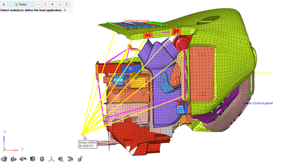 Figure 5.
 -
Select all degrees of freedom.
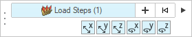 Figure 6.
 -
Click .
The Static loadcase with the load collectors and other entities required for the simulation is created. Respective load collectors get created and are assigned to the loadstep.
Import model and Results File
In this step, you will use the SnRD Post to post process the results.
-
Select .
The SnRD Post Processing tool opens.
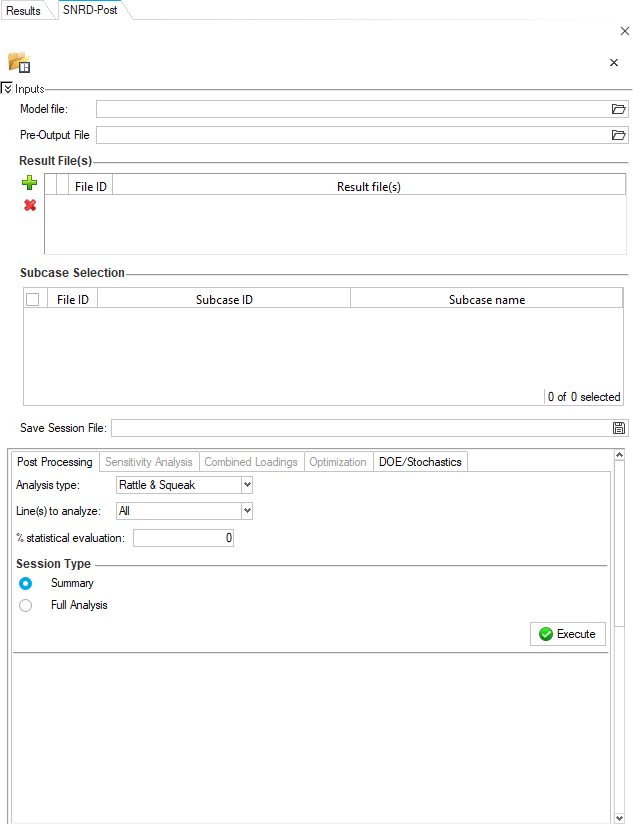 Figure 7.
 -
Using the file browse option
 , select the OptiStruct solver file which was exported in Export OptiStruct Solver File for Model File.
Note: Pre output CSV file containing the E-Lines definition is sourced automatically.
, select the OptiStruct solver file which was exported in Export OptiStruct Solver File for Model File.
Note: Pre output CSV file containing the E-Lines definition is sourced automatically. -
Click
 .
A file browser window will appear.
.
A file browser window will appear. -
Click
 in the Save Session File entry
field.
in the Save Session File entry
field.
-
Browse and select the required folder where the post processing session and
data will be stored.
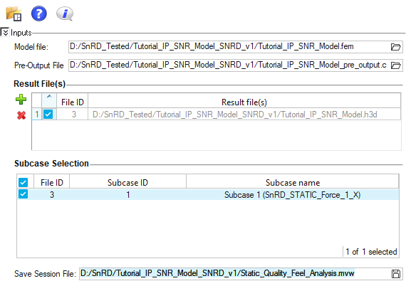 Figure 8.
Post Processing
In this step, you will perform Full Analysis to understand the squeak and rattle risks in the model.
-
Click Execute.
Note: Execution of the Full Analysis will take a considerable amount of time to chart histograms and plot contours based on the machine's performance.An execution success message opens.
 Figure 9.
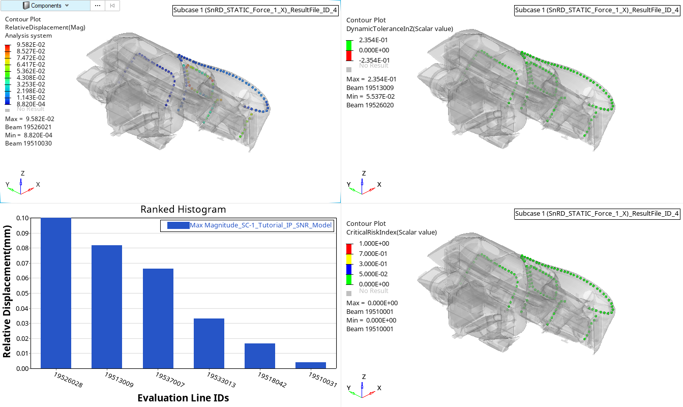 Figure 10. Rattle Summary Linear
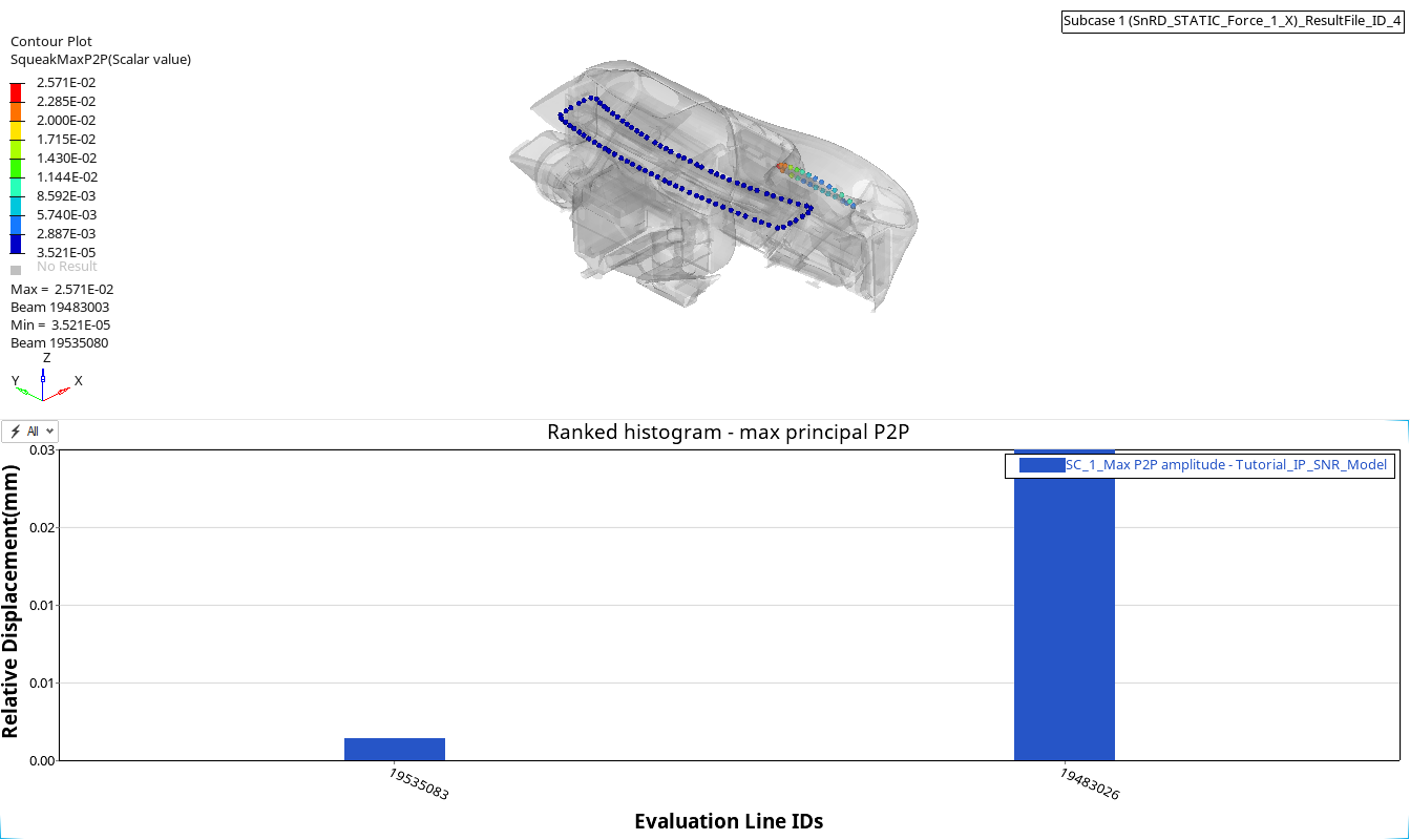 Figure 11. Squeak Summary Linear
From the results, you can observe that there are no squeak and rattle issues in the model for the applied static force. You can verify the issues by increasing the force amplitude and re-run the post processing.