Basic Screening Risk Analysis
Use SnRD to identify squeak and rattle issues.
This tutorial describes the basic screening analysis that the S&R analyst would perform. Starting from a NVH FE-model, the analyst wants to define a first set of Evaluation-lines (E-Lines) to assess the S&R performance of a system. Typically, this first analysis will occur at the early stage of the virtual development process, thus a lack of input might be a road blocker for the S&R CAE engineer. Therefore, the SnRD simple process will close this gap by offering automation and a set of default settings enabling this first analysis.
- Interface to be analyzed
- Detailed Gap, dimensioning and tolerance data
- Loading Conditions
The objective of this tutorial is to create E-Lines to evaluate squeak and rattle, define a SineSweep loadcase, and evaluate risks.
Import Model
In this step, you will use the Import tool to import the required set of files.
-
Click Import.
The selected model is imported to the session.
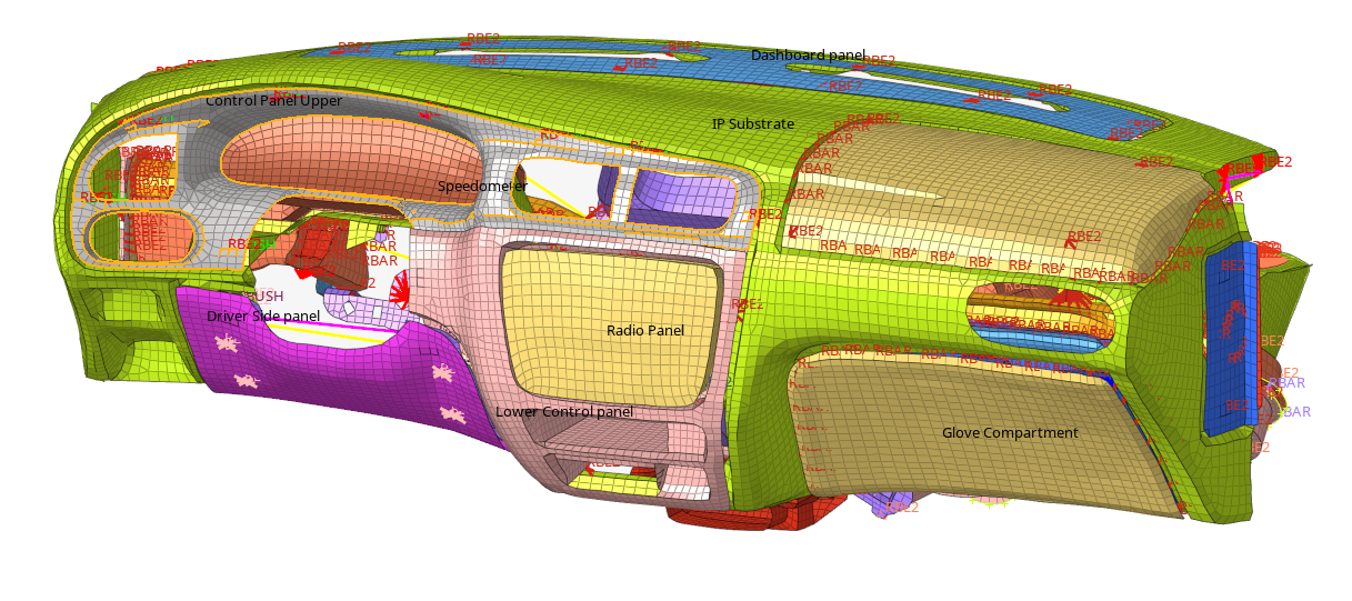 Figure 1.
Create Geometric Lines
In this step, you will define the interface between components by using the Create Geometric Lines tool to create geometric lines in the model.
-
On the HyperMesh View toolbar, click
 , and select
QuickReviewComps.
, and select
QuickReviewComps.
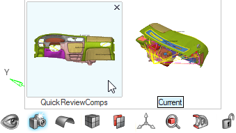 Figure 2. The components you want to include in the evaluation are isolated.
 -
From Setup group, select Define
Interface.
 Figure 3. A guide bar opens.
 -
From the guide bar, click
 to open advanced options.
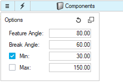 Figure 4.
 -
Click
 .
The geometric lines are created at the component edges in the model. Twelve lines should be created.
.
The geometric lines are created at the component edges in the model. Twelve lines should be created.
Create E-Lines
In this step, you will create and manage all the E-Lines in the model.
-
From Setup group, select Create
E-Line tool.
 Figure 5. A guide bar opens.
 -
Click .
Eleven E-Lines are created in the model.
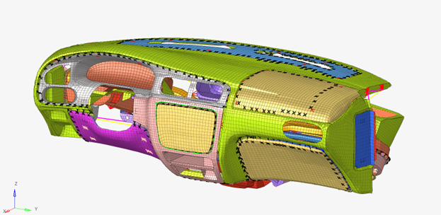 Figure 6.
Manage E-Lines
In this step, you will use the Manage E-Lines tool to review E-Lines in the model.
-
From Setup group, select .
 Figure 7. The Review E-Line dialog opens containing a table.
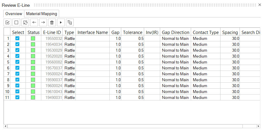 Figure 8.
SineSweep Loadcase Setup
-
From Setup group, select Dynamic
Event.
 Figure 9. A guide bar opens.
 -
From the guide bar, click to view advanced options.
-
For Output Frequency under Time Step, enter 4.
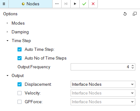 Figure 10.
 -
In the graphics area, select the node shown in Figure 11.
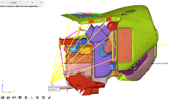 Figure 11. A microdialog opens.
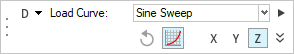 Figure 12.
 -
Click .
The SineSweep loadcase is created. The Curve Editor dialog opens.
-
Setup Constraints for the other Degree of freedoms (DOFs) on the same node
using:

Figure 13. -
In the microdialog, select the loadcase which was just created
(SnRD_Dyn_Disp_#_Z) and Lock all DOFs beside Z translational.
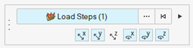
Figure 14. -
Click .
Export OptiStruct Solver File
-
From Analyze group, select Export OptiStruct
Solver File.
 Figure 15. The Model Export dialog opens.
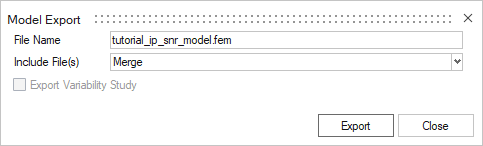 Figure 16.
Risk Assessment
In this step, you will evaluate risks for Squeak and Rattle in the Risk Assessment.
-
Open Risk Assessment.
 Figure 17.
 -
Click Plot.
The Relative Displacement for the E-Lines are visualized.
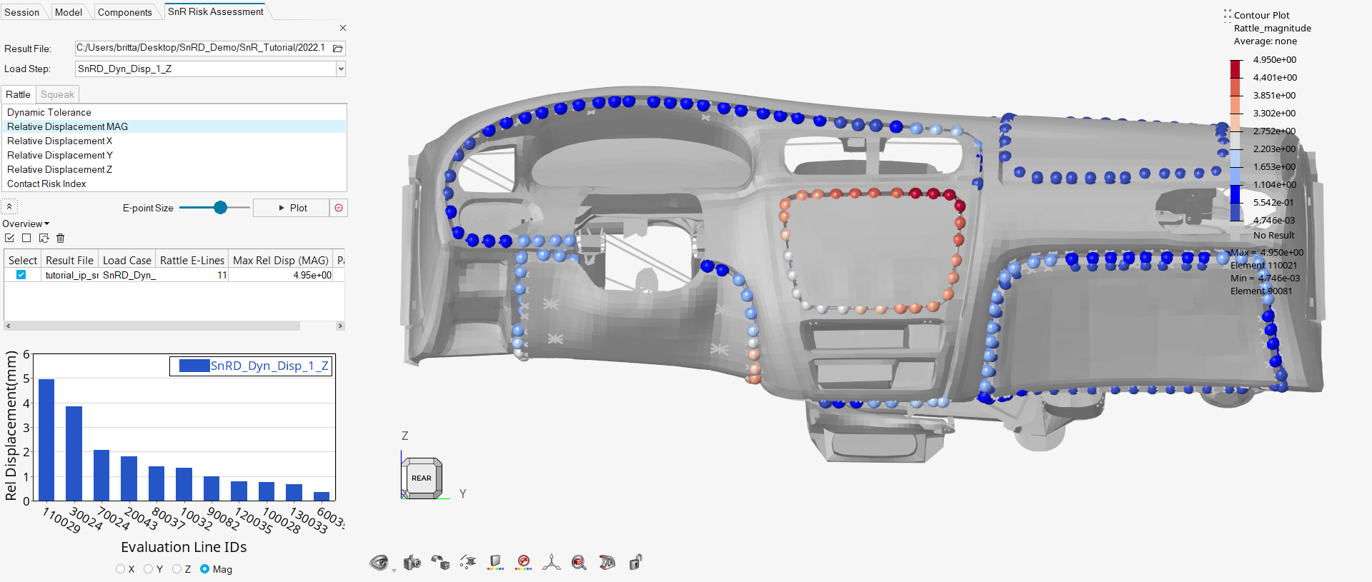 Figure 18.
 - Optional:
Review the summary of all E-Lines in the model for the
active loadcase and result file by clicking
 .
Tip: If loading results are from additional result files and loadcases, then these results will be appended to the Summary Table which allows you to conduct easy comparisons of design iterations.
.
Tip: If loading results are from additional result files and loadcases, then these results will be appended to the Summary Table which allows you to conduct easy comparisons of design iterations.
Generate Summary Report
In this step, you will export a squeak and rattle summary report using the Report tool.
-
Enter a name for the report and select which results to include.
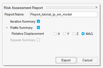 Figure 19.
 -
Review the report.
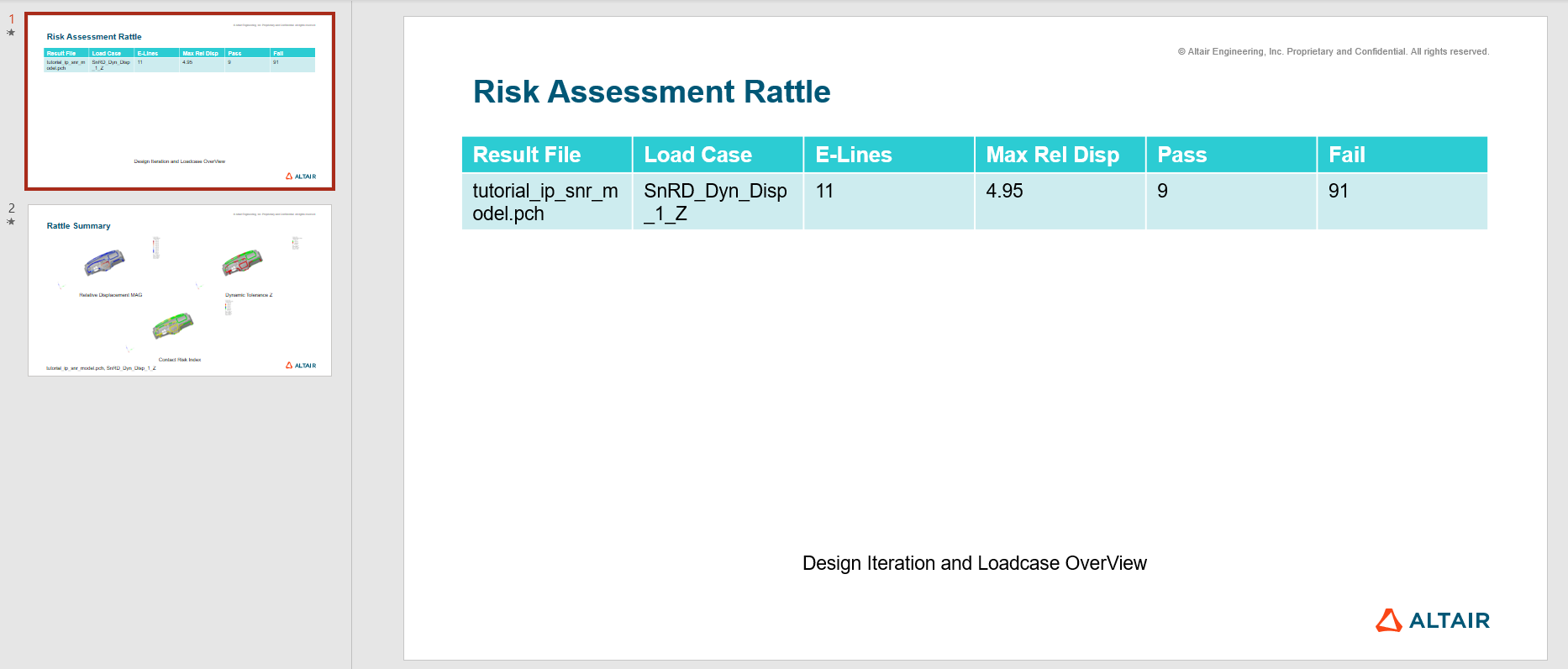
Figure 20.