
Specify Heat Exchangers
Identify the inflow, outflow, inertial resistance, and viscous resistance of heat exchangers, which are modeled as a porous medium.
Identify the heat exchangers in one of the following ways: as a series of
in/out surfaces or as a single solid. Setting up a single solid heat exchanger is
more straightforward but requires you to define the permeability
direction.
-
Use the Identify Heat Exchanger tool. You can
choose to define each part of the heat exchanger solid, or define the solid as a
whole. To define the heat exchanger using in/out surfaces:
-
From the Setup ribbon, click the
Identify Parts tool.
Figure 1. 
-
From the secondary tool set, click the Heat
Exchanger tool.
Figure 2. 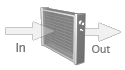
-
Specify the inflow component.
- From the Identify Heat Exchanger tool, click the In arrow.
- Select the corresponding component.
Figure 3. 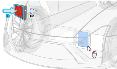
-
Specify the outflow component.
- From the Identify Heat Exchanger tool, click the Out arrow.
- Select the corresponding component.
Figure 4. 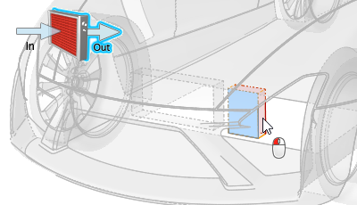
In general the heat-exchanger is modeled as a rectangular volume. As soon as the inlet and outlet of the heat exchanger are defined, VWT automatically identifies the connecting wall between those two surface regions.
- Optional:
Manually define the connecting wall.
- From the Identify Heat Exchanger tool, click the Wall icon.
- Select the corresponding component.
Figure 5. 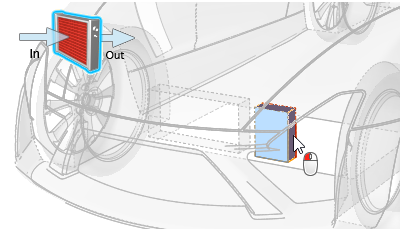
-
- Constant heat
- Applies a constant heat through the heat exchanger, defined in W.
-
- Fluid temperature
- Simulates a fluid moving through the heat exchanger, defined in K.
-
- Coolant temperature
- Simulates a coolant moving through the heat exchanger. This
thermal mode requires more properties to be defined, as well as
selecting a reference surface.
Figure 6. 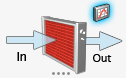
Figure 7. 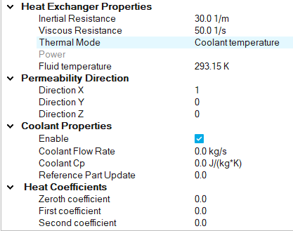
-
From the Setup ribbon, click the
Identify Parts tool.
- Right-click on a part in the modeling window or the Model Browser and select from the context menu.
- Select a part in the modeling window or the Model Browser then change the Identify As field to Heat Exchanger Inlet/Outlet/Wall in the Property Editor.
-
To define the heat exchanger as a whole solid:
-
Click the
 icon in the Heat Exchangers dialog.
-
Define the permeability direction in the Property Editor when creating a single solid heat
exchanger.
Figure 8. 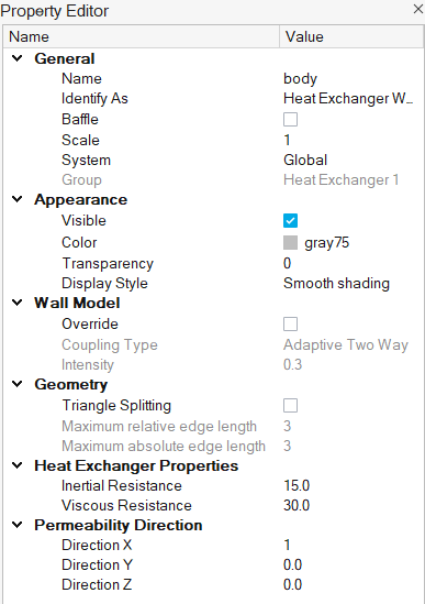
-
Click the
Tip:
- Open the Property Editor and review the parameters associated with a particular heat exchanger by left-clicking on parts identified as a heat exchanger in the Model Browser. Heat exchanger properties that can be set include: inertial and viscous resistance, permeability direction, and thermal properties.
- Define additional heat exchangers by clicking in
the Heat Exchangers dialog. This will increase an
internal index to number all heat exchangers.
- Use the right-click context menu in the Heat Exchangers dialog to delete and rename heat exchangers.