
Define the Belt System
Use the Belt System tool to model a belt system.
-
From the Setup ribbon, click the Belt System tool.
Figure 1. 
By default, five patches are created on the wind tunnel ground for modeling the belt system.Figure 2. 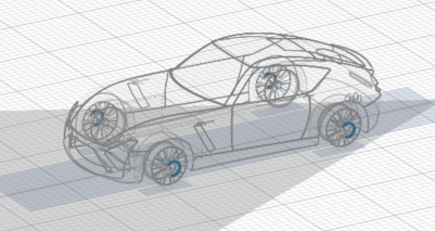
-
Define the belt system's location and sizes in the following ways:
- Edit belts individually by selecting a belt in the Model Browser or modeling window
and modifying its properties in the Property Editor.
Figure 3. 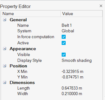
- Edit the belt system by clicking Belt System
tool satellite icon
 .
.Figure 4. 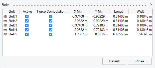
Note: The belts are synchronized, so adjusting a parameter on one belt will automatically apply the same change to the others in the system.
- Edit belts individually by selecting a belt in the Model Browser or modeling window
and modifying its properties in the Property Editor.
Note: The solver will always respect the settings for
boundary layer suction. Any portion of the ground that is upstream of the boundary
layer suction location will be treated as a slip wall.