
Specify Fans
Identify the components that represent fans in the model.
Fans are modeled like wheels, a boundary condition is prescribed and a rotational speed is applied.
You select the parts that form the fan, such as blades and hub. The center and axis of rotation are automatically computed. However, the rotational speed needs to be provided.
Aerodynamics and aeroacoustics supports four model approaches for fans:
- Frozen
- The fan does not rotate in the simulation.
- Overset
- The fan and mesh inside is rotated to accurately represent the flow and rotating fan.
- MRF
- The fan does not rotate in the simulation. An MRF volume improves the modeling of the swirling flow created by a fan.
- Virtual
- Applies a body force to a volume to mimic a fan. There are three types
of virtual fans:
- P-Q curve (originally called Virtual)
- Velocity
- Mass flow rate
Figure 1. 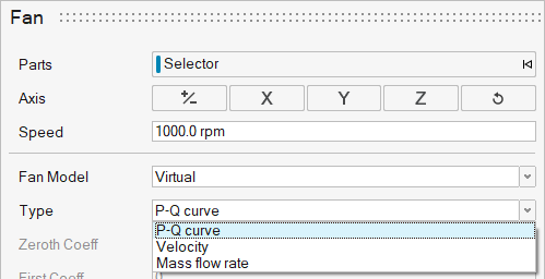
-
From the Setup ribbon, click the
Identify Parts
tool.
Figure 2. 
-
From the secondary tool set, click the Fan tool.
Figure 3. 
The Fan dialog opens. -
Select a part to define as the fan/volume.
The axis and speed automatically populate based on the part selection.
- Optional: Adjust the axis and speed.
- Select the Fan Model from the following options:
Note: Steps 6-7 are only for Overset and MRF.
-
Create a volume around the fan by completing one of the following:
Choice Selection Import a previously created volume - Select Select.
- Browse, select, and import the previously created volume.
Create a cylinder volume - Select Cylinder.A tightly wrapped cylinder volume is automatically created around the fan.Tip: You can adjust the size of the cylinder by selecting the diameter or height labels in the modeling window and entering a new value in the microdialog.
Figure 4. 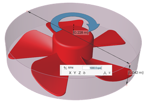
Create a Solid Revolution volume - Select Solid Revolution.A CAD geometry is automatically created around the fan.Tip: You can adjust the offset size by entering a new value for Offset. If the Offset is too large, a warning will be given.
Figure 5. 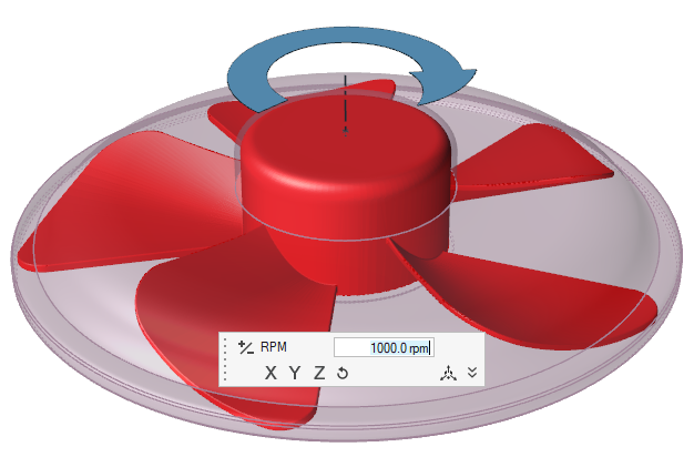
Figure 6. 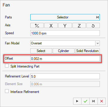
- Optional:
To check for and split intersecting parts, enable the Split
Intersecting Part checkbox.
A color coded legend displays which indicates any intersecting, interior, and exterior parts. When the fan is created, the intersecting parts are split.
Figure 7. 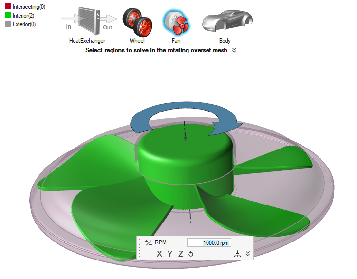
Note: Step 8 is only for Overset.
-
Adjust the Refinement Level of the interface refinement.
The Element Size is adjusted automatically.
Note: Step 9 is only for Virtual.
-
Specify the body force coefficients for the volume.
The solver automatically calculates radius and depth. This information is available when you export the run results to .xml.
Note: Step 10 is only for Overset, MRF, and Virtual.
-
Adjust the Refinement Level.
The Element Size is adjusted automatically.
Note: Steps 11-13 are for Virtual fans only.
- Select between P-Q curve, Velocity, and Mass flow rate.
- Specify the Ramp Up Iterations, i.e., the number of discrete iterations, based on the coarsest refinement level, for which the ramp-up is active. (If a valid pressure rise value is given, <num_ramp_up_iterations> will be set to 200 by default; otherwise to zero).
-
Specify the initial conditions.
- For P-Q curve fans, specify the Initial Pressure Rise, i.e., the targeted/estimated initial pressure rise of the fan.
- For Velocity fans, specify the Velocity.
- For Mass flow rate fans, specify the Mass Flow.
Note: This functionality requires a valid value for the parameter <depth> to be set; otherwise, the initial pressure rise cannot be taken into account.
Step 14 is for Frozen, Overset and MRF fans only, and only if thermal
functionality has been enabled.
- Optional:
Under Temperature BC, choose between Adiabatic and
Temperature BC type.
- If Temperature, set the desired temperature.
Note: Activate thermal functionality by enabling Thermal Model in the Run dialog. -
Complete one of the following:
- Select
 to confirm your
selections and continue specifying fans.
to confirm your
selections and continue specifying fans. - Select
 to confirm your
selections and exit the dialog and tool.
to confirm your
selections and exit the dialog and tool. - Select
 to clear your
selections and start over.
to clear your
selections and start over. - Select
 to exit the
tool without confirming your selections.
to exit the
tool without confirming your selections.
- Select