
Specify Wheels
Identify the components that represent wheels in the model.
You need to select the parts forming the wheel, for example tire and rim. All other parameters like center of rotation, axis of rotation, and the angular velocity (in RPM) are computed automatically.
-
From the Setup ribbon, click the
Identify Parts
tool.
Figure 1. 
-
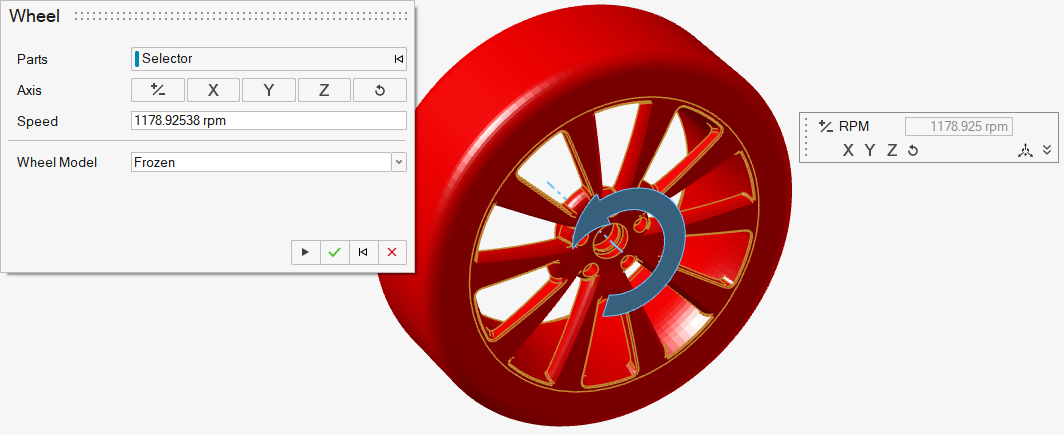
From the secondary tool set, click the Wheel tool.
Figure 2. 
The Wheel dialog opens. -
Select parts to define as the wheel.
The axis and rotational speed automatically populate based on the part selection.
- Optional: Adjust the axis and speed.
-
Select the wheel model from the following options:
- Frozen
- OverSet
- MRF
Note: Steps 6-8 are only for OverSet wheels.
- Click to select the overset mesh from the model.
- Define the mesh control parameters.
- Define the interface refinement parameters.
Note: Steps 9-10 are only for MRF wheels.
- Click to select the overset mesh from the model.
- Define the mesh control parameters.
- Optional:
Under Temperature BC, choose between Adiabatic and
Temperature BC type.
- If Temperature, set the desired temperature.
Note: Activate thermal functionality by enabling Thermal Model in the Run dialog. -
Complete one of the following:
- Select
 to confirm your
selections and continue specifying wheels.
to confirm your
selections and continue specifying wheels. - Select
 to confirm your
selections and exit the dialog and tool.
to confirm your
selections and exit the dialog and tool. - Select
 to clear your
selections and start over.
to clear your
selections and start over. - Select
 to exit the
tool without confirming your selections.
to exit the
tool without confirming your selections.
- Select