
Define Heat Exchanger Components
Use the Heat Exchanger tool to specify heat exchanger components for a solid.
It is useful to model a heat exchanger if you have coolant properties, friction properties, and effectiveness data available. An alternate way to model heat exchanger components is by defining a porous media with a heat source.
-
From the Flow ribbon, click the arrow next to the
Domain tool set, then select
Heat Exchanger.
Figure 1. 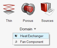
-
Select a solid body.
Note: Only one solid selection is allowed.
-
Click Inlet on the guide bar then
select the inlet surface of the exchanger.
Note: Only one inlet surface selection is allowed. If the inlet of the heat exchanger solid consists of multiple surfaces, merge them before using this tool.
The Merge tool is accessed from the Geometry ribbon by clicking the arrow next to the Edit tool group name.
-
In the microdialog, use the two tabs to define heat
exchanger thickness, coolant properties, friction properties, and effectiveness
data
In the Advanced tab, define friction and effectiveness types in the following ways:
Option Method Constant and Kays London Enter values in the text boxes. Piecewise Linear and Cubic Spline - Click
 .
. - In the variable editor dialog, define the X axis using the Curve fit variable drop-down menu.
- Use the table and plot area to input function data.
User Function - Click .
- In the variable editor dialog, enter a function expression.
- Select an argument from the drop-down menu.
- Use the table to input data.
- Click
-
From the guide bar, execute the command in the following
ways:
- Click
 to confirm your selection and remain in the
tool.
to confirm your selection and remain in the
tool.This allows you to continue creating instances and helps you visualize and edit instances with the legend.
- Click
 to confirm your selection and exit the
tool.
to confirm your selection and exit the
tool.
- Click