AcuTrace

AcuTrace is particle tracer that runs as a post-processor to AcuSolve.

Figure 1.


AcuTrace computes traces for unsteady as well as steady flow fields, for flows with mesh motion as well as without, and for flows computed on meshes with interface surfaces.

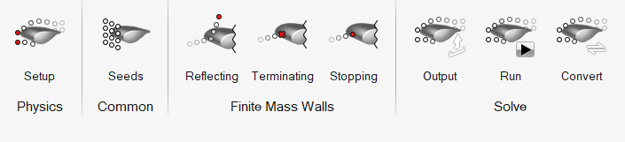
The following describes how to use the AcuTrace ribbon as a whole.

  1. Set up and run an AcuSolve model.
  2. Open the AcuTrace ribbon.
  3. Define particle tracer settings.
    1. Set the particle type to Finite mass particles or Massless particles.
    2. Setup of particle tracing assumes that the AcuSolve run is finished. Point to the ACUSIM.DIR directory.
      Upon selection, the last run in the directory is referenced. You can change the problem name and run ID. It is recommended to not have too many AcuSolve runs in same folder.
    3. Define maximum time, maximum segments, and flow field type.
    4. If using Finite mass particles, define particle properties in the Finite-mass setup tab.
  4. Define particle seeds to inject in the domain.
    1. If the AcuSolve run was set up in HyperMesh CFD, open the .hm file first so that you can directly position particles on geometric surfaces.
    2. If the AcuSolve run was made using other UIs and reference geometry is not available:
      1. Load the AcuSolve run log file in post.
      2. Use the Probe tool to define points.
      3. Export the .csv file.
      4. Import the .csv file in AcuTrace and define points.
    3. Define emission start, stop, intervals and density and radius for finite mass particles.
  5. If using Finite mass particles, define reflecting, terminating, and stopping walls.
    1. Based on the selected run, relevant flow boundaries are available for selection. Select the appropriate boundaries.
      Note:
      • No selection highlights or conflict resolution are made for these tools, so you have to choose your selection carefully.
      • If the model setup is done in HyperMesh CFD, change the visualization color to “Boundaries” to get references.
    2. For reflecting walls, define the co-efficient of restitution.
  6. Define Trace output and Time cut output settings.
  7. Run AcuTrace.
    Point to the AcuTrace executable and define run settings.
    Note: The installed versions of AcuTrace and AcuSolve must be the same.
  8. Open the Convert tool.
  9. Define the AcuTrace path, log file for the AcuTrace run, and output format and data. Get an ensight file to post-process using the HyperMesh CFD Post ribbon.
  10. Optional: Load the AcuTrace ensight file to see both AcuSolve run boundaries and particles.
    1. You can define color settings for particles and vector settings attached to particles.
    2. You can animate particles as well.