Solution

Define output conditions, run the simulation, and view the results.

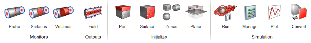
Attention: The icons shown on the ribbon below are used to complete this workflow. Click an icon to learn more about the tool.
Surface monitors for all defined boundaries are created automatically. However, additional surface monitors can be created using the Surfaces tool. Volume monitors for all defined domains are created automatically. However, additional volume monitors can be created using the Volumes tool. Use the Field tool to define nodal output for the entire model. Use the Run tool to define run settings and submit an AcuSolve job. Use the Manage tool to track solver and meshing jobs. Use the Plot tool to track converged and derived solution behavior in real time. Use the Probe tool to monitor time history data on defined points at specific time intervals. Use the Part tool to define initial conditions on all nodes (boundary + volume nodes) of selected solids. Use the Surface tool to define initial conditions on all nodes of selected surfaces. Use the Zones tool to define initial condition on all nodes enclosed within defined zones. You can define boxes, spheres, and cylinders as zones. Use the Plane tool to select solids and define initial conditions on either side of a plane. Use the Convert tool to convert AcuSolve run data to tabular text file data, h3d, AcuFieldView, EnSight, and CGNS format.