
Define Fan Components
Use the Fan Component tool to model a fan by specifying fan characteristics on a solid.
-
From the Flow ribbon, click the arrow next to the
Domain tool set, then select
Fan Component.
Figure 1. 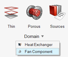
-
Select a solid body.
Note: Only one solid selection is allowed.
-
Click Surfaces on the guide bar then select the inlet
surface of the exchanger.
Note: Only one inlet surface selection is allowed. If the inlet of the fan component solid consists of multiple surfaces, merge them before using this tool.
The Merge tool is accessed from the Geometry ribbon by clicking the arrow next to the Edit tool set name.
- Click Axis on the guide bar.
-
Left-click in the modeling window to place the axial
direction of the fan.
Tip: Use snap points to position the axis on existing points, lines, surface centers, etc.
-
Use the options in the microdialog to further align the
axis.
- Click
 to flip the rotation
direction.
to flip the rotation
direction. - Click X, Y, or Z to align to the global axes.
- Click
 to position the axis
using the Vector tool. Once the position is
defined, press Esc to return
to the current tool.
to position the axis
using the Vector tool. Once the position is
defined, press Esc to return
to the current tool.
- Click
-
In the microdialog, define the method, the type of fan,
fan thickness, and fan characteristics parameters – axial, radial, tangential
force parameters, or P-Q curve.
- A P-Q curve can be defined using a table and plot.
- A P-Q curve is a two-dimensional array which defines the fan performance curve with the first column representing flow rate in m3/s and the second column representing pressure increase in Pa.
-
From the guide bar, execute the command in the following
ways:
- Click
 to confirm your selection and remain in the
tool.
to confirm your selection and remain in the
tool.This allows you to continue creating instances and helps you visualize and edit instances with the legend.
- Click
 to confirm your selection and exit the
tool.
to confirm your selection and exit the
tool.
- Click