
Define Orientation
Several tools require you to define a plane or a vector direction to perform a certain function, such as dragging geometry along a vector, spinning it about an axis, or splitting it with a plane. The Plane and Vector tools are used to define and edit planes and directions.
Plane Tool
Define an orientation using the Plane tool in the following ways:
-
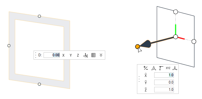
Pick an initial orientation from the suggested global X, Y, or Z frames.
Resetting the plane selector shows these initial suggestions again.
Figure 2. 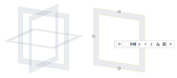
Tip: Some planes can be resized (finite) while others cannot (infinite). Infinite planes do not allow dragging their handles to resize or rotating them about their normal axis. -
Click and drag the frame area to reposition it along its normal direction using
snaps or a distance value.
Use the options in the microdialog to help position the plane or change its options:
- D
- Distance offset value.
- X, Y, Z
- Align the plane to the corresponding global axis.

- Invoke the Vector tool (see below) for advanced plane editing.

- Toggle the plane representation between a frame (default) and a filled rectangle.
- Center
- Plane center coordinates.
-
Click and drag the rotator arrows on the sides of the plane to rotate it around
that axis. The rotator arrows appear when approaching the handles on the sides
of the plane.
Use the options in the microdialog to help rotate the plane:
- θ
- Angle offset value.
- -90, -45, 0, 45, 90
- Angle increment shortcuts.
-
Resizable (finite) planes have handles on all sides and corners and can be
dragged to resize in any direction. They also have in-plane rotators that appear
near the corner handles.
Figure 3. 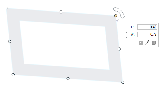
Tip: While resizing, hold Ctrl to resize from the center, and Shift to lock the aspect ratio.Use the options in the microdialog to help resize a finite plane:
- L, W
- Plane dimensions.

- Toggle to resize from the center (Ctrl).

- Toggle to lock aspect ratio (Shift).
- Toggle the plane representation between a frame (default) and a filled rectangle.
Vector Tool
Define an orientation using the Vector tool in the following ways:
-
Click and drag to move the base handle – the point in space where the
plane/vector is located. Then, drag the handle at the tip of the arrow to define
a vector, or drag two handles on the edges of the plane to define a plane.
The application takes advantage of the following principle: a plane can be defined with a vector (the plane is normal to the vector specified), just as a vector can be defined with a plane (the vector is normal to the plane specified).
Figure 4. . Example defining a vector using the plane handles. A spin axis is defined normal to 3 locations on a circle. 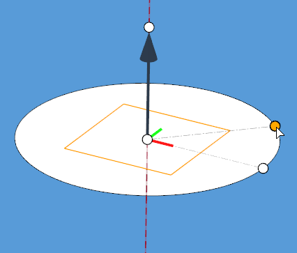
Figure 5. . Example defining a plane using the vector handles. A split plane is defined normal to a point and its perpendicular projection to an edge. 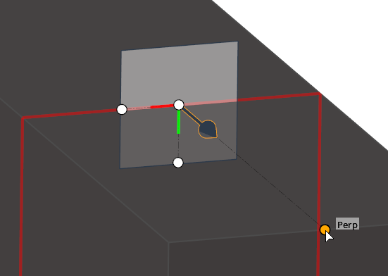
- Instead of dragging the handles with the mouse, you can also define a plane/vector quickly by holding Ctrl and clicking on any two locations for a vector, or any three locations for a plane.
-
Use the options in the microdialog to help position the
vector or plane.
 ,
,  ,
, 
- Align to one of the global axes, or type any vector components.

- Translate or rotate the Vector tool with precision.

- Edit handle coordinates.

- Reverse the direction of the vector.

- Align the vector/plane as normal or parallel to the current view.

- Select a Vector entity to align to, or assign a local coordinate System. After a new system is assigned, the Vector tool automatically repositions to its origin.
Tip: When a local system is assigned to the Vector tool, the system button is shown with a tick mark , indicating that the manipulator is now in
local system mode. Click this button again to change the assigned system
or reset it to go back to global system mode.
, indicating that the manipulator is now in
local system mode. Click this button again to change the assigned system
or reset it to go back to global system mode.