
Create and Edit Lines
Use the Create Lines tool to draw free lines for geometry construction and to generate meaningful snap locations to be used by other tools.
-
From the Geometry ribbon, click the arrow next to the
Create tool set, then select
Create Lines.
Figure 1. 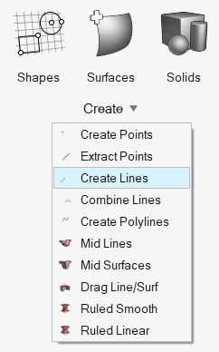
- Optional:
From the guide bar, click
 and select Enable topology
color mode.
The next time the tool is opened, topology color mode will be enabled automatically.
and select Enable topology
color mode.
The next time the tool is opened, topology color mode will be enabled automatically. -
From the drop-down menu, select one of the following:
Option Description Interactive - Draw a line.
- Left-click on geometry or in space to create the line's start point.
- Move your mouse to draw a line.
- Left-click to create the line's end point.
- Resize the line by editing the length in the microdialog and pressing Enter.
- Double-click on a free line to edit the length.
Extract Parametric Lines Create lines at parametric locations on surfaces. - From the guide bar, select Surfaces to select a surface that the parametric values are in reference to.
- From the microdialog, define the following:
- Along U
- Specify the number of lines created between the
lower and upper u bounds.
- If specified as 0, no lines are created along the u direction.
- If specified as 1, a line is created at the lower u bound only.
- If specified as 2, lines are created at both the upper and lower u bounds.
- If specified > 2, lines are created at linear intervals between the lower and upper u bounds.
- Along V
- Specify the number of lines created between the
lower and upper v bounds.
- If specified as 0, no lines are created along the v direction.
- If specified as 1, a line is created at the lower v bound only.
- If specified as 2, lines are created at both the upper and lower v bounds.
- If specified > 2, lines are created at linear intervals between the lower and upper v bounds.
-
Figure 2. This example uses a range of 0 to 0.75 with 5 u lines, and a range of 0 to 0.5 with 4 v lines. 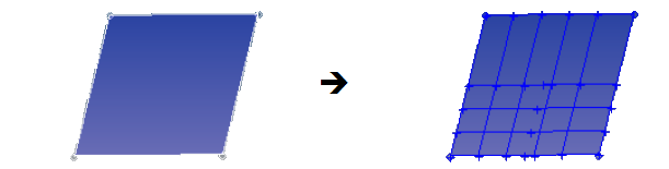
- Auto-imprint
- 1D elements drawn on FE geometry remesh the surface; on CAD geometry, they imprint an edge.
- From the guide bar, click to define the following options:
- U lower bound
- Specify a value that >= 0.0.
- U upper bound
- Specify a value that is <= 1.0.
- V lower bound
- Specify a value that is >= 0.0.
- V upper bound
- Specify a value that is <= 1.0.
- Create in
- Choose a method for organizing the resulting lines.
- From the guide bar, click one of the
following:
 - Apply and stay in the
tool
- Apply and stay in the
tool - Apply and close the
tool
- Apply and close the
tool - Exit the tool without
applying
- Exit the tool without
applying
Extract at Intersection Create lines at the intersection of geometric entities. - From the guide bar, select the type of
geometry to intersect.
Valid combinations include lines/plane, surfaces/plane, elements/plane, plane/plane, and surfaces/surfaces.
- Select geometry in the modeling window.
- For line/plane intersections, select the Smooth lines check box to create smooth curves.
- For elements/plane intersections, click to define the
following options:
- Create type
- Combine lines: create single line segments.
- Break Angle
- Specify where the intersection line will remain segmented. Segments with an angle relative to each other that exceed this angle will not be combined and will remain separate line segments.
- From the guide bar, click one of the following:
- - Apply and
stay in the tool
- - Apply and
close the tool
- - Exit the
tool without applying
Drag Nodes Create lines by dragging nodes a specified distance along a vector. - Select nodes to drag.
- Pick an initial orientation from the suggested global X, Y, or Z frames then fine tune the direction along which to drag the node.
- Specify the length of the line.
- From the guide bar, click one of the following:
- - Apply and stay in the
tool
- - Apply and close the
tool
- - Exit the tool without
applying
A line is created at each node by dragging the nodes the specified distance along the given vector.
- Draw a line.
- Draw lines that are perpendicular or tangent to other lines by snapping to
predefined points such as end, middle, center, and intersection points. You
can also snap to points along the x, y, and z axis.
Dashed lines hint to the location of snap points on surfaces and lines. Hovering over snap points along the x, y, and z axes matches the line's color with the color of the corresponding axes in the lower left corner of the modeling window.
- Hold Ctrl to create multiple chained
lines.Note: Even though the lines are connected by their position, each segment will still be an independent line entity.
- Copying and pasting surface edges generates free lines and organizes them in the same component.