
Extrude Geometry
Extrude surfaces, nodes, or lines along their normal direction, a vector, or another line.
-
From the Geometry ribbon, click the arrow next to the
Create tool set, then select Drag
Line/Surf.
Figure 1. 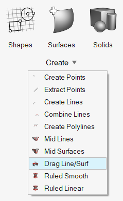
- Optional:
On the guide bar, click
 to define additional options.
-
Choose between Surfaces,
Nodes, or Lines using the guide bar selector.
Note: If Nodes is selected, a line is drawn through the specified nodes before dragging.
-
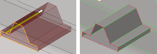
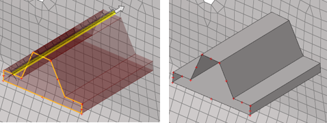
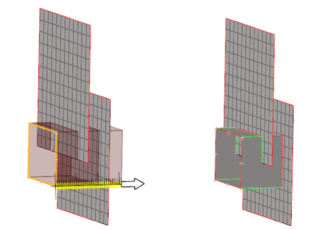
Select surfaces/nodes/lines and drag in the
following ways:
- Use the drop-down in the microdialog to drag at a fixed normal distance or at a variable distance.
- Click
 to define a direction using the Vector tool. Once a direction is defined, manipulate the
slider or enter a value in the microdialog.
to define a direction using the Vector tool. Once a direction is defined, manipulate the
slider or enter a value in the microdialog. - Activate the Guides selector to drag along selected guiding lines.
Use the options in the microdialog to define how the
geometry is dragged.
- Fixed Frame
- The geometry is only translated during the drag, not rotated.
- Line Tangent
- In addition to the translation of the fixed frame option, the geometry is also rotated in the same way that the tangent of the line list rotates.
- Frenet Frame
- In addition to the translation and rotation of the Line
Tangent option, the geometry also rotates around the line
list tangent axis in the same way as the curvature vector
rotates.
The Frenet Frame option does not work well when the curvature of the line list is not smooth or includes large jumps.
- Reverse Direction
- Defines the drag in the opposite direction.
- Check Create mesh to automatically open the 2D meshing tool after creating surfaces. After you finish meshing, exit the tool to return to Geometry.
-
On the guide bar, complete one of the following:
- Click
 to apply and stay in the tool.
 - Click
 to apply and close the tool.
 - Click
 to exit the tool without applying.
- Click
A drag preview for FE geometry solids is not supported at this time.
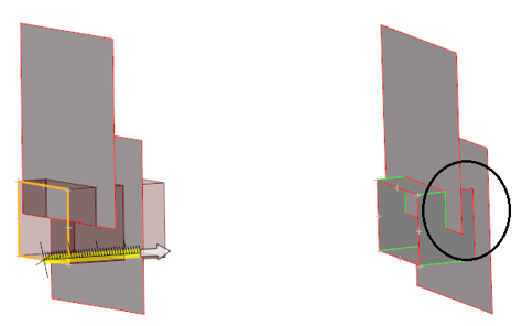
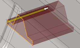
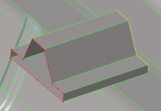
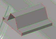
Auto-Trim
Use the auto-trim ![]() option in the microdialog when extruding nodes and lines.
option in the microdialog when extruding nodes and lines.
While extruding lines or nodes, if a continuous surface or mesh is intersected and this option is ON, the newly created surfaces are trimmed at the intersection. The auto-trim option works for both geometry intersecting geometry and mesh. It also works for FE topology intersecting FE topology.
 |
 |
 |