
Define Trim, Pierce and Lance Lines
After adding a trim operation to your analysis, you can define trim, pierce and lance lines.
-
Select a Trim operation that you added to your analysis.
The Trim, Pierce, and Lance tools appear on the Tryout ribbon.
Note: If your model includes a single trim line, the software automatically identifies it. If more than one trim line exists, the longer line is identified as a trim line and the remaining lines are identified as pierce lines. - Select the Trim, Pierce, or Lance tool.
-
On the model, select the line(s) or edge(s) where you want to create the trim,
pierce or lance line.
Note: This is extracted from the Middle face by default. You can select Top or Bottom in the guidebar.
-
Click to confirm or on the guide bar, click
Assign.
The trim, pierce and lance lines are assigned. An arrow appears for each line indicating a direction for the trimming process. The default direction is based on the average normal.
Figure 1. Model with Trim and Pierce Lines 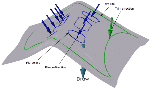
Figure 2. Model with Lance Line 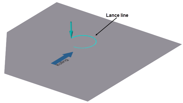
Change the Position of Trim, Pierce, or Lance Lines
Adjust the position of the trim, pierce, or lance lines relative to the blank.
-
On a Trim operation you added to your analysis, click lick the Edit
Position
 tool.
tool.
 A guide bar opens with auto and manual options.
 -
Choose:
Software Position Description Auto The blank moves to the trim line automatically. Manual On the model, select and drag the manipulator to move the trim line in reference to the blank. The manipulator indicates the distance from the selected tool relative to the blank.
Alternatively, in the microdialog, enter a value for the distance.
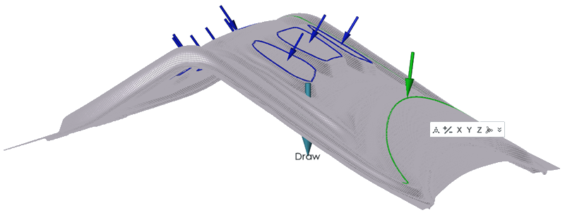
Change the Direction of Trim, Pierce or Lance Lines
Define the direction of the trim, pierce or lance lines.
- On your model, double-click an arrow that points to a trim, pierce or lance line.
- Use the microdialog options to define the line direction.
Microdialog Options
Select from the options to define the direction of the trimming or piercing process.
| Icon | Description |
|---|---|
 |
Manually define the draw direction with the manipulator that appears on the model. |
| Reverse the draw direction. | |
 |
Align the draw direction to the global X, Y or Z axes. |
 |
Align to part |
 |
Review the value for the the global X, Y or Z axes. |
Keyboard Shortcuts & Mouse Controls
| To | Do this |
|---|---|
| Add/remove from selection | Ctrl+click |
| Reverse selection | Ctrl+R |