Configure a Drawbead
Designate a part or surface(s) on your model for the drawbead.
-
From the Tryout ribbon, select a forming operation that you've added to your
analysis.
The tool set for the operation is displayed.
-
Next to the tool set, click the Add Tool
button.
-
From the Add Tool dialog that appears, double-click the
Drawbead tool.
- On the model, select the tool where you want to attach the drawbead.
- Click to confirm.
- Select the line(s) or edge(s) where you want to create the drawbead.
-
Click to confirm, or click Create on the guide
bar.
- If you make multiple selections for drawbeads, on the guide bar, click Assign to create the drawbeads for all of the selected lines.
Note: If the drawbead requires an offset, on the guide bar, select the Offset check box, then click Create, or click to confirm. In the microdialog, type in a value for the offset. The default is the sheet thickness plus 20%. -
In the microdialog that appears, enter values for the drawbead
parameters:
- RF (restraining force)
- CF (closing force)
- Type: select Rectangular, Circular or Step
-
To further calculate and define the parameters for the drawbead, click
.
-
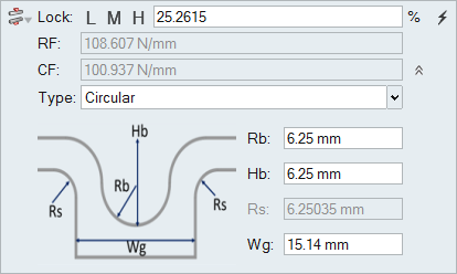
In the expanded microdialog, enter values for these drawbead parameters:
radius, height, groove shoulder radius, and groove width.
The values you enter are calculated and populated for the restraining and closing force.
-
To lock the material at a particular percentage, to the left of the field
RF click the arrow to expand options for controlling
the restraining and closing force. Enter a value or select a preset button
L (low) 20%, M (medium) 50% or
H (high) 80%.
Note: The drawbead shoulder radius is automatically modified to match the desired lock percentage.
-
Move outside of the microdialog, and click to confirm the configuration of the
drawbead.
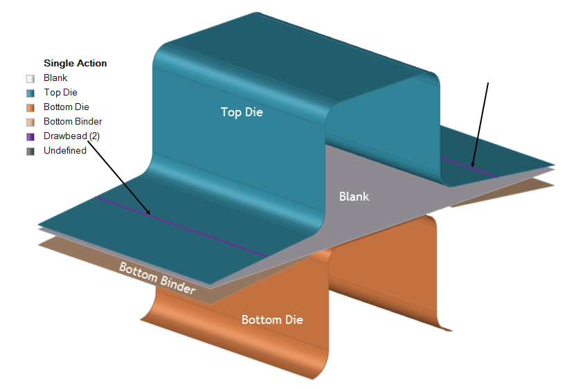
Figure 1. Example of a Drawbead in a Single Action Operation 
Keyboard Shortcuts & Mouse Controls
| To | Do this |
|---|---|
| Add/remove from selection | Ctrl+click |
| Reverse selection | Ctrl+R |