Since version 2026, Flux 3D and Flux PEEC are no longer available.
Please use SimLab to create a new 3D project or to import an existing Flux 3D project.
Please use SimLab to create a new PEEC project (not possible to import an existing Flux PEEC project).
/!\ Documentation updates are in progress – some mentions of 3D may still appear.
Working environment of the circuit editor context
Introduction
The electric circuit editor is a context dedicated to the physical context. It has a working environment similar to the standard Flux context.
The Circuit Editor Context window
The general window of the electric circuit editor context comprises several zones. These different zones are identified in the figure below.
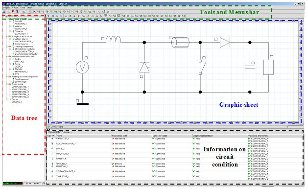
Role of zones
The various zones and their main role are briefly described below:
| Element | Function |
|---|---|
| Tools and menus bar | All the functions of the electric circuit editor are available starting from the different menus and tools bars |
| Data tree |
The tree comprises the circuit data classified by entity. These data are also visible in the data tree available in the standard context. It is possible to edit or modify a component through a contextual menu from this tree. |
| Graphic sheet |
The graphic sheet consists in a grid:
Graphic tools of the electric circuit editor context: zoom and displacement are available in this sheet permitting the actions of zoom and displacement. |
| Information regarding the electric circuit condition |
The information of the circuit is presented in a table with two tabs:
This information indicates to the user the condition of the electric circuit, element by element. |