Since version 2026, Flux 3D and Flux PEEC are no longer available.
Please use SimLab to create a new 3D project or to import an existing Flux 3D project.
Please use SimLab to create a new PEEC project (not possible to import an existing Flux PEEC project).
/!\ Documentation updates are in progress – some mentions of 3D may still appear.
The various components of the electric scheme
Introduction
An electric scheme is a graphic representation of an electric circuit.
The various components of the electric scheme are:
- the components
- the wires or connections
- the junctions or the connecting points
the electric potentials (or equipotentials)
Components
The components are chosen in a library of components.
From a graphic viewpoint, they are represented by the following symbols:
| Voltage/current sources | Current
source
|
Voltage
source
|
||||
| Components of field-circuit coupling | Coil
conductor
|
Solid
conductor
|
Solid
conductor N pins
|
|||
| R, L, C components | Resistor
|
Inductor
|
Capacitor
|
|||
| Switch and Diode | Switch
|
Diode
|
||||
| Rotating machine components | Brush-segment
|
Squirrel
cage
|
||||
| Masse | ||||||

Connection
A connection is the representation of an electric wire.
From a graphic viewpoint, a connection is a sequence of segments and of changes of direction, between a starting point and an arrival point.
The authorized starting points and the arrival points are:
- the terminals of the component
- the extremities of the connection
- the angle of a change of direction of the connection
- the connecting points
Connecting point
A connecting point is an intersection between wires with electric contact.
From a graphic viewpoint, a connecting point is represented by a point in bold.
Electric potential
From a graphic viewpoint, an electric potential regroups the elements with the same potential (assembly of connections and of connecting points).
This is not about defining the quantity called electric potential.
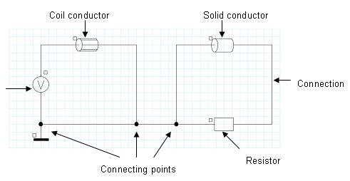
Example: electric scheme on sheet
Let us take the example of a simple electric circuit.
The circuit components are represented on the electric scheme on the drawing sheet (figures below).
Example: representation of the tree of components
We are interested in the previous circuit example.
The circuit components are listed in the display zone corresponding to the components tree (figure below).
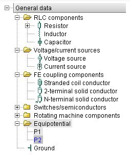
The components tree comprises:
- the list of components
- a coil conductor B1
- a resistor R1
- a solid conductor M1
- a voltage source V1
- the list of potentials
- 3 equipotential entities, numbered as P1, P2, P3
- the Z1 ground point