Adding Waveguide Ports
Define waveguide ports with the correct orientation.
Note: A port is a mathematical representation of where energy can
enter (source) or leave a model (sink). Use a port to add sources and discrete loads to
a model.
Waveguide ports without sources are considered to be absorbing waveguide terminations.
-
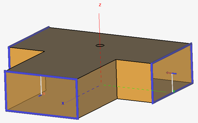
Add the first waveguide port on the face at the most positive X position.
-
In the 3D view, repeatedly left-click until the
face is highlighted.
Figure 1. The face at the most positive X position is selected. 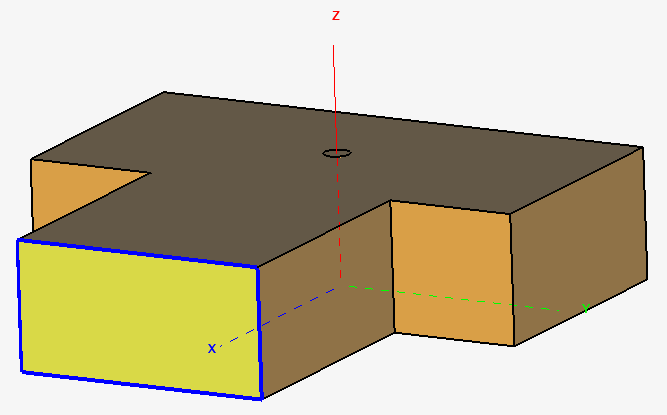
-
Open the Create Waveguide Port dialog using one of
the following workflows:
- On the Source/Load tab, in the
Ports group, click the
 Waveguide Port icon.
 - In the details tree, a right-click context menu is available on the face. From the list, click .
Figure 2. The Create Waveguide Port dialog. 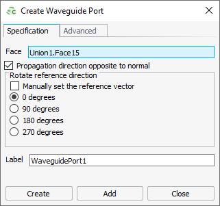
- On the Source/Load tab, in the
Ports group, click the
-
Use the default settings for the port.
Figure 3. The preview of the waveguide port is displayed in green. 
Note: The white line is the reference vector and shows the direction of m, where m is the number of half-wavelengths across the width of the waveguide.
-
In the 3D view, repeatedly left-click until the
face is highlighted.
-
Add the second waveguide port at the face at the most negative Y
position.
- On the dialog, click on the Face user input field to make it active. An active field is highlighted in blue (see Figure 2).
- In the 3D view, repeatedly left-click until the face is highlighted.
- Click Add to add the waveguide port, but do not close the dialog.
-
Add the third waveguide port at the face at the most positive Y position.
- On the dialog, click on the Face field to make it active. An active field is highlighted in blue.
- In the 3D view, repeatedly left-click until the face is highlighted.
- Click 180 degrees to ensure the correct reference direction.
- Click Create to add the port and to close the dialog.
-
Enable the port annotations. On the 3D View
context tab, on the Display Options tab, in the
Entity Display group, click the
 Port Annotations icon.
Figure 4. The waveguide power divider with three defined waveguide ports.